
10 Sensors, Safety, Analog and Troubleshooting
We now look outside the control panel at devices and methods of design that affect the design of the PLC and the overall project. Included in this chapter are sensors, a separate study of safety of the machine and the operator, machine vision, bar-code and RFID, analog signal acquisition, troubleshooting techniques and diagnostic circuits. We end the chapter with a short discussion of other ‘stuff’ and some articles on design and opinions about machine safety from some experts.
SENSORS
An important area is the discussion of sensors and sensor types. Many times the sensor and the application of the sensor are as critical to the success of a project as the PLC program. Web- sights such as www.sensorsmag.com, www.flowcontrolnetwork.com and www.globalspec.com provide search engines for information about various types of industrial sensor types.
A good website for an organization dedicated to instrumentation and sensor advancement is the International Society of Automation’s website .
Allen-Bradley lists a number of types of sensors in their website:
- Automatic Float Switches
- Connection Systems Drum Switches
- Encoders and Resolvers
- Limit Switches
- Liquid Level Switches P
- hotoelectric Sensors
- Pressure Controls – General Industrial
- Pressure Controls – Traditional Machine Tool Proximity Sensors
- Rotating Cam Limit Switches
- Speed Switches
- Temperature Control
- Ultrasonic Sensors
Siemens likewise contains similar sensor types to Allen-Bradley and can offer sensors for most industrial applications. The following page(s) list only one type of Siemens sensor (for pressure). The list is rather long and shows the diverse nature of the sensor industry with each type of sensing requiring a great deal of investigation in order to provide the best possible device for the application at a competitive price.
Importance of Sensors
Sensors are important in the overall design of any control system and the engineer/technologist must be aware of their importance to have a successful control system. Cost is always a factor as well as safety and maintainability. Something as simple as level measurement is not always simple. With the example of sensing level in a tank, it can be seen that the methods and costs vary over a wide range. It is also important to consider whether temperature, humidity or other physical change will upset the device. Also to be considered are changes in density, composition, moisture and other physical characteristics. Accuracy and repeatability are also considerations. The factor that the material may or may not have to actually touch the sensor may need to be considered as well. Some powders are especially difficult to handle and sense.
If the powder cakes or is chunky or granular, the sensor may require special techniques for sensing.
Devices such as tanks or silos with level control are an example of the sensors described that are chunky or granular. Level sensing in a tank may involve a number of different considerations including the following list. In the Liptak book “Process Measurement and Analysis”, the author(s) divides the level selection guide into nine different categories:
- Liquid
- Liquid/Liquid Interface Foam
- Slurry
- Suspended Solids
- Powdery Solids
- Granular Solids
- Chunky Solids
- Sticky Moist Solids
The number of different types of sensors is 21 from the same book with some of the types having a number of different sub-types. The list of methods to measure various physical continues to grow and increase in sophistication.
From Liptak’s book, the following are methods used to sense level in a vessel.
- Beam Breaker
- Bubbler
- Capacitance
- Differential Pressure
- Electromechanical Diaphragm
- Displacer
- Float
- Float/Tape
- Paddle Wheel
- Weight/Cable
- Gauges/Glass
- Gauges/Magnetic
- Inductive
- Microwave
- Radiation
- Sonic Echo Sonar
- Sonic
- Ultrasonic
- Thermal
- Vibration
While the reader may quickly conclude that one of the sensor types is superior to another, the fact that so many different types are present suggests that different sensors may be useful for a specific type of application and be a failure in another application. Cost also is also of high importance in the selection of a sensor, especially if the number of sensors increases to a large number. Reliability and maintainability are also considerations for the purchaser.
Photo-eye Technology
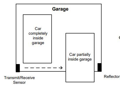
Photo-eye technology has advanced greatly over the years and can be used to sense a great number of different devices. Used primarily to sense discrete devices, the photo-eye has been used to sense, among other things, the presence of an automobile in the garage door, effectively blocking the door from coming down on a moving or partially parked automobile. The figure below shows what would happen if a car were not protected by a photo-eye system. The car on the right would not be protected from an overhead garage door coming down on it if the photo- eye were not present. The car blocks the signal from the transmitter at left. The reflector does not see the light and the receiver responds with no light signal from the reflector. The light from the transmitter is unique in that another source such as a flashlight or the sun will not trigger a response other than from the photo-eye’s own transmitter.
The following discussion of photo-eye types shows the breadth of usage for some types of sensors. The little photo-eye is not just used for the simple garage door application. They are useful in a number of very different types of applications with more applications being developed each year. The following discussion gives the reader some idea as to the specialization that even the simple devices can have. The photo-eye is ideal to study since it is useful over a range of applications and because it is relatively inexpensive. It does not have a high price tag but has many different types of modes with some having sub-modes of the various modes themselves. This gives a sophistication that is not present in the garage door photo-eye switch.
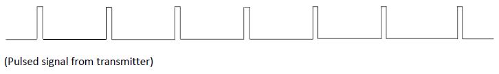
The infrared LED is pulsed at a rate from the transmitter and sensed at the receiver. Only the pulsed signals are accepted at the receiver. This blocks all other light sources which in prior years contaminated the photo-eye receiver. No longer does the afternoon sun change the signal sensed at the receiver.
An Application of Photoelectric Devices
At the Banner Engineering website is a separate manual explaining the theory and practice of applying photoelectric devices to part sensing. Banner Engineering was innovative in their discovery of the modulated LED sensor for part sensing.
Included in their manual are discussions on sensing modes including:
- Opposed Mode
- Retro-reflective Mode
- Proximity Mode
- Diffuse Mode
- Divergent Diffuse Mode
- Convergent Mode
- Fixed-Field Mode
- Adjustable-Field Mode
- Fiber Optic Modes
- Ultrasonic Proximity Modes
The catalog also includes a number of applications with a suggested method of sensing the devices for the application.
A review of some of the concepts of infrared photoelectric sensing are reviewed below:
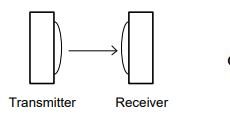
In the opposed mode, emitter and receiver are housed separately. An object is seen when the beam breaks. A disadvantage to the opposed mode is that electrical power must be supplied to two separate locations, an added cost.
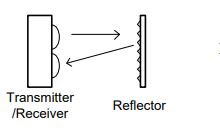
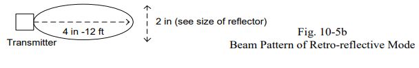
In the retro-reflective mode, the emitter and receiver are housed in the same unit. A reflector is located opposite the emitter and reflects light back into the receiver. An object is seen when it breaks the beam as with the opposed mode.
Proximity Mode
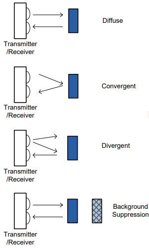
In this mode, the sensor contains both emitter and receiver. Objects are detected when light is reflected from the object back to the receiver. The following four types of proximity mode can be used based on the device being sensed and the background around the device.
The following definitions for range are described in the Banner manuals. The range for each mode is as follows:
- Opposed mode: Distance from emitter to receiver
- Retroreflective mode: Distance from emitter to reflector
- Proximity mode: Distance from emitter to object sensed
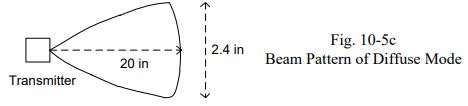
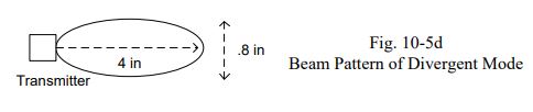
Also described for each sensor is a specific beam pattern and excess gain chart. These will be shown for various types of sensors. The beam pattern describes how the light falls around the object. A narrow beam pattern is usually desired over a more diffuse beam pattern although in some applications, a diffuse pattern is preferred. The excess gain describes a ratio of the amount of light at the receiver divided by the minimum light necessary to operate the sensor successfully.
Characteristics of the Various Modes:
Opposed Mode: For the opposed mode, the excess gain graph on the left shows a linear response. The beam pattern shows a wide angle. Other characteristics of opposed mode include:
Retro-reflective Mode
For the retro-reflective mode, the excess gain graph on the left shows a parabolic response. The beam pattern shows a wide angle similar to the opposed mode. Other characteristics of retro- reflective mode include;
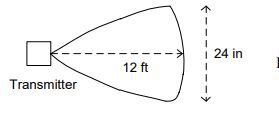
Diffuse Mode
For the diffuse mode, the excess gain graph on the left shows a gain linear over large distances and flat for smaller distances. The beam pattern shows a wide angle similar to the opposed mode. Other characteristics of the diffuse mode include:
Divergent Mode
For the divergent mode, the excess gain graph shows a parabolic gain similar to the retro-reflective mode. The beam pattern is narrower than others discussed. Other characteristics of the divergent mode include:
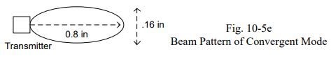
Convergent Mode
For the convergent mode, the excess gain graph shows a very narrow range of detection allowed. The beam pattern is narrow and ranges from a few mm to no detection as distance increases. This can be useful if a background object is to be ignored. Other characteristics of the convergent mode include:
Background Suppression
This mode is similar to the convergent mode in that the range of detection is limited. No beam pattern is given for this mode. Other characteristics of this mode include:
- Backgrounds can be ignored
- In the range of detection, high gains can be obtained
- Targets of varying reflectivity may be detected
While the use of photo-electric sensors is not simple, a proper analysis usually gives a best fit of the type of sensor to be used.
Prox Switch
Another popular switch is the proximity switch. This switch can be found in a number of configurations, mostly though as the inductive prox switch.
This switch was invented to replace the limit switch, especially in cold climates when limit switches froze solid in winter. The prox switch has no moving parts and senses presence or absence of metal, ideal for sensing valve position in out-door tank farms.
See the list below of some of the various sensors offered by the Turck Company. Turck started as a prox switch manufacturer and branched into all the sensors seen here:
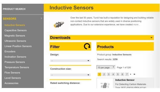
From the Turck Catalog:
New this month, an Inductive Safety Sensor with two OSSD (output switching signal device) outputs. The sensors send switching signals to safety systems via their OSSD outputs. This is used to easily detect short circuits, overloads or cross-connections while simultaneously testing the shutdown capabilities. With SIL 2 and Performance Level D ratings, these sensors meet stringent functional safety requirements. The wide temperature range of -25°C to 70°C and IP67 rating make these ideal for use in safety-related applications such as compactors, machine covers, and monitoring of doors in safety zones.
Machine Vision
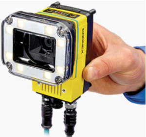
A sensor that is costly but offers many benefits is the machine vision system. The Cognex vision system offers the complete system of vision inspection for industry. Their hardware and software offer the manufacturer an inspection system capable of solving many of the hard inspection problems.
The University of Toledo was given the opportunity to purchase Cognex equipment through a grant from the state of Ohio.We purchased eight Cognex 7802 vision systems. These systems gave the opportunity to explore the Cognex inspection process in depth. It was determined to use the hardware in classwork to inspect for the following:
- PatMax Pattern Recognition
- Histogram
- Edges
- Blobs
Cognex software may be used in either the online or simulate mode. In the simulate mode, an entire process may be built and tested without hardware. Both methods are acceptable to learn the software listed but with actual hardware, the hands-on learning of the 7802 system give students the experience of a real system complete with lighting or lack of lighting and how the part can be seen most clearly.
RFID VS BARCODES: Advantages and disadvantages comparison
Manufacturers currently employ two forms of automated data collection: barcodes and RFID systems. There is much hype as to whether RFID will end up taking over the barcode industry. One data collection method is not essentially better than the other.
An application that barcode cannot do is the floating database of many transfer machines in which an operation is carried out at a station and the next station depends on the prior operation to successfully perform its operation. Each station must read the present status of the part (usually on a pallet) and then perform its operation and, if successful, write the new status on the rfid tag. The rfid tag then, at the end, has the entire history of the operations performed on the part written on the pallet tag.
This type of operation is not dependent on multiple plcs transferring information between each other. They only require the read-write communications capability to the rfid tag.
RFID tags can also be used in more harsh environments than the bar code tag. For example, the tags used on livestock are rfid tags placed in the ear of a calf or hog allowing the animal to be followed throughout their growth and eventual end in the rendering plant. The present RFID tags used in the livestock industry are low-frequency tags that are read at a radio frequency ofn134.2 kHz (kilohertz). In the beef industry, the tags contain a 15- digit alpha-numeric (numbers and letters) code called the Animal Identification Number (AIN). This 15-digit AIN is also printed on the outside of the tag.
The standard for livestock readers is ISO 11784/11785. The functions of readers are to transmit and receive radio frequency signals, contain a control unit to execute commands, incorporate an interface to transfer data, and receive and respond to commands from a computer. Some readers only store the data (15-digit AIN) and require that the information will be manually downloaded to a computer. Other readers are able to send data directly to a computer or palm pilot.
The following give a review of one of the RFID tag systems from Siemens.
The following RF300 mode transponders can be used with the SIMATIC RF300 RFID system:
The Machine Directive
Some of the directives are covered in an article by Linda Caron & Parker Hannifin[1]
The Directive mandates the use of commonsense safety strategies on machinery, such as the use of e-stop buttons, the removal of air in a machine to protect against unexpected movement where safe to do so and the addition of technical measures where risk cannot be designed out. Additionally, to meet enhanced safety levels on machinery, redundancy and monitoring must be included in the controls of the machine in accordance with EN ISO 13849-1, as well as validation of the system in accordance with EN ISO 13849-2.”
She continues: “EN ISO 13849-1 provides safety requirements and guidance on the principles for the design and integration of safety-related parts of control systems (SRP/CS), including the design of software. EN ISO 13849-2 specifies the procedures and conditions to be followed for the validation by analysis and testing of the specified safety functions, the category achieved, and the performance level achieved by the safety-related parts of a control system (SRP/CS) designed in accordance with ISO 13849-1.”
Machine Safety in Canada
NFPA 79 is a standard used by industry in the United States to define safety standards in machine control. C22. 2 N°301 is the reference standard for the Electrical Equipment of Machinery in Canada. The international standard is IEC 60204-1.
CSA Standards – CSA on Demand
- Add access Info
To design any system, a plan has to be generated to identify what it is that the system is supposed to do. If one were to design a safety system:
- The FUNCTIONS of the safety system has to be defined
- The OBJECTIVE of the safety system function is to REDUCE RISK
- The HAZARDS need to be defined for each MODE of OPERATION of
the machine to meet the objective
- Functional requirements will be defined by sequencing of the machine, the
requirements of the risk assessment, the types of components and subsystems
within the system and the standards requirements - The design of the functional aspects of the system can encompass:
- Mechanical, Electronic and Fluid Power Guarding Systems
- System, circuit and component performance requirements
- Safety Controls and Circuit Performance requirements are specified by Standards
- The Function of a safety system is to monitor and control conditions on a machine or process that are hazardous in themselves or, if no action were taken, may give rise to hazardous situations
- The Safety System runs in parallel with the Production System
- Focus of Production System is Throughput
- Focus of Safety System is Protection
- A Safety system is designed to protect (in the following order):
- People
- Environment
- Machinery/Equipment
- A Safe Application is defined as a situation where the residual risk is at or less
than the accepted risk.
- Jan 23, 2019 ↵
