Chapter 2 Lab and Exercises
Introduction to Lab 2.1
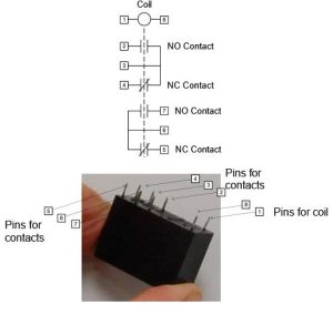
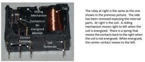
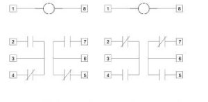
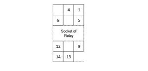
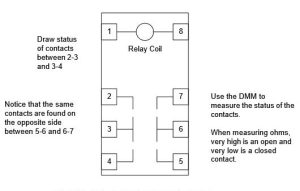
There are a number of different types of relays made today. The type shown below has a coil at the top and two sets of contacts at the bottom. The sets of contacts are referred to as ‘Form C’ contacts since the common terminal and the two opposite terminals can be drawn in the shape of a ‘C’:

The coil voltage for the relays used in lab 1 is 12 V DC. To energize the coil, apply +12 VDC to terminal 1 and 0 VDC to terminal 8. The relay would work equally well if the voltages were switched between the two terminals 1 and 8 such that + 12 VDC is terminated on 8 and 0 VDC on terminal 1.
Care should be taken to verify the contact arrangement. Sometimes, the contact arrangement of the relays may be reversed. In other words, the normally open contact is between 3-4 and 5-6. The normally closed contact is between terminal 2-3 and 6-7. The student should check to determine which type of relay contact is available before using the relay. It is also good to check the pushbuttons (PB’s) to determine which pushbuttons have normally open contacts and which have normally closed contacts.
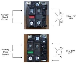
Instead of incandescent lights, a LED and a resistor may be used. It is installed as follows:

Care must be taken to install the LED with the proper polarity. If it does not work when first tested, turn it around and test again. The 1KΩ resistor is used to limit current below the upper current threshold of the LED.
Alternate Relay (24 VDC)
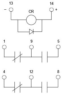
Another type of relay is now available in the lab for use, the Omron MY2N-D2 pictured here:
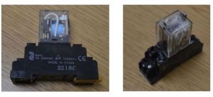
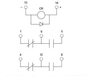
This relay has a 24 VDC coil. The coil is labeled (+) on terminal 14 and (-) on terminal 13. Note the diode which is used as a fly-back diode to minimize current when the coil is being turned off. Contacts are shown below the coil similar to the contacts of the 12 V relay.
The base of the Omron relay is pictured below.
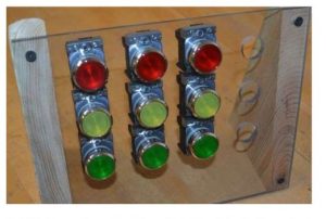
Also, the student may use the new pushbutton stations for this lab including the normally closed red buttons and the normally open yellow and green buttons. Wiring of these buttons is shown in Figure 2-40 below. Normally open are labelled NO and colored green. Normally closed are labelled NC and colored red.
Indicator lights are incorporated into the pushbuttons. Terminals for the lights are labelled X1 and X2. These lights will illuminate with either the 12 V or 24 V power supplies. They are located on the right side of the figure below and labelled X1-X2.
Lab 2.1 Introduction to Ladder Logic
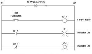
Wire the following circuit and describe what happens when the switch closes:
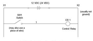
The following is used only for the 12 VDC Relay:
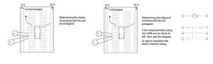
Describe the contact position of the normally open and normally closed contacts of the control relay coil when the switch position is open, closed.
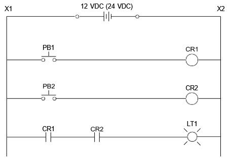
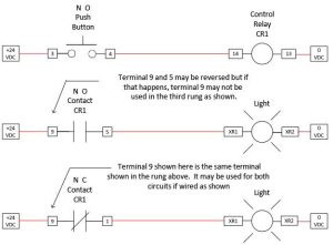
2.1-1 Wire the following circuit and observe what happens when the button is pushed:
Wire this circuit using the contacts on relays, pushbuttons and lights shown in Fig. 2-41 above and using 24 V relays. Wires shown in red are actual wires to be added by student.
2.1-2 Describe observations of Fig. 2-45 before the pushbutton is pushed and when the pushbutton is pushed.
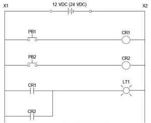
Wire the following circuit and observe what happens when the buttons are pushed:
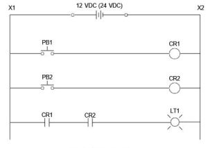
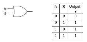
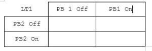
2.1-3 Construct a table similar to Table 2-2 showing when either push button is pushed or not pushed, the state of the light. To what type of circuit from digital logic would the output of Table 2-2 be equivalent?
2.1-4 Change the circuit so that CR2 uses a normally closed contact in the circuit for the light as follows and fill in the table similar to Table 2-2 again.
Change the circuit to the one as follows:
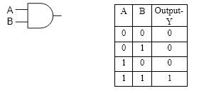
2.1-5 Fill in a table similar to Table 2-2 showing the state of the light when either push button is pushed or not pushed. To what type of circuit from digital logic would the output of Table 2-2 be equivalent?
Wire the following circuit and observe what happens when the buttons are pushed:
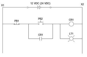
2.1-6 Describe observations when PB 2 is pushed and PB 1 is not pushed in Fig. 2-47. What happens when PB 1 is then pushed?
Add a second PB 2 in parallel to the original PB 2.
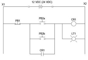
2.1-7 Describe observation when PB 1 and PB 2 (A or B) are alternately pushed. Next add a second PB 1 in series to the original PB 1.
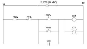
2.1-8 Describe observation when PB 1 (A or B) and PB 2 are alternately pushed.
Lab 2.2 AC Voltage Starters and Logic
This lab provides two motor starters with 24V DC or 110 VAC coils and sufficient selector switches and push buttons to wire the two starters for a reversing operation. Design and wire a circuit that will seal in the Forward or Reverse motor starter contactor in the run mode and will allow a jog function in the jog mode. Provide a stop button that will stop the motor.
To start wiring a motor starter circuit, consider the following:
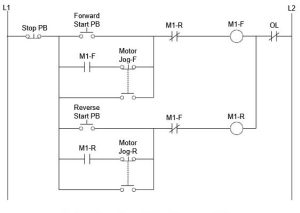
Here ‘Jog’ enables the motor to turn on when the button is pushed but turn off if the button is released. Jog can be used with a slow speed to be used for positioning if the motor is multi- speed but in this example, jog and run speeds are the same. To make this circuit work as designed, the contacts must be “break-before-make” for the jog switch. If this is not the case with your push button, you may achieve the same effect by slowly pushing the jog button.
Lab Directions
Lab 2.2 A
Wire the circuit above for one motor starter deleting the reversing function.
Lab 2.2 B
Wire the circuit above or equivalent for two motors starters incorporating the reversing function. Use either one stop push button or two stop push buttons.
Lab 2.2 C
Wire the circuit per Fig. 2-27.
Lab 2.2 D
Wire Lab 2.2 A including an indicator light for motor running.
Lab 2.2 E
Wire Lab 2.1 B including indicator lights for forward and reverse.
Lab 2.2 F
Wire Lab 2.2 C including indicator lights for forward and reverse.
To complete Lab 2.2, use the motor starters from the lab and push buttons from the PLC trainers to wire a circuit that will provide the functions described above for the starter or starters.
Lab 2.2-1
Draw the complete circuit including the 3 phase motor starter and the control circuit used in Fig. 2-42. Use the resources in this chapter to find an appropriate 3 phase motor starter circuit. Be neat. Assign wire numbers for all wires in the ladder portion of the circuit.
Exercises
Converting from Digital Logic Functions to Ladder Logic:
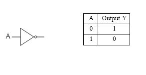
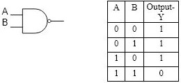
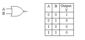
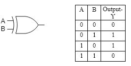
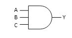
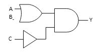
Construct ladder equivalent circuits of each of the following digital logic functions. Use normally open and normally closed contacts of A and B to construct the appropriate function:
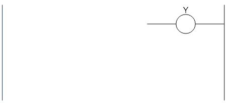
Use the following ladder diagram figure for exercises 1-6.
Questions
- Find a copy of a specification written to purchase a piece of equipment. What does a specification accomplish?
What parameters do you suppose were part of the original PLC specification? - What kind of PLC would you expect to find in a Japanese-owned automotive plant in the United States? – German-owned automotive plant in the United States?
- Draw the ladder logic equivalent of:
- *Draw the ladder logic equivalent of:
- What physical device in the bathroom resembles the liquid level switch?
- Draw logic for a motor starter control circuit for a motor that is either off, on forward or on reverse with a selector switch.
- Draw the control portion of a motor starter circuit for a forward only motor starter with start and stop push buttons located at 2 different locations.
- *Draw the control portion of a motor starter circuit for a forward only motor starter that turns on with either a start button and stays on until stop is pushed or may turn on when the PLC output turns on. A selector switch chooses whether to use the PLC output or the start pushbutton. A stop button turns the motor off either way. Label all devices appropriately.
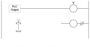
Fig. 2-51 Partial Circuit for Problem 2-14 - 15. *Draw logic for a motor starter control circuit for a motor that is turned on with a jog button in either the Forward or Reverse direction. When the operator releases the jog button, the motor stops in either the Forward or Reverse direction. Draw only the control portion of the motor starter circuit.
- *Observe what happens when the buttons are pushed:
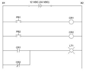 Fill in the table:
- In 2014 General Motors had a press conference with reference to ‘the switch from hell’. What was the underlying problem with this switch and why did the switch almost cause GM to go bankrupt? The switch is shown in the figure below:

- Fill in all terminal designations for both Control Relays below. Reference contacts given below: