Want to create or adapt books like this? Learn more about how Pressbooks supports open publishing practices.
Chapter 6 Exercises
Exercises
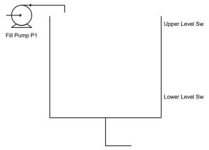
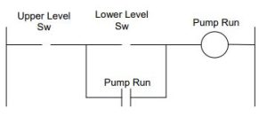
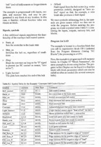
Finish the evaluation of the logic in Table 6-4.
The tank is now being filled automatically from the pump. When the tank is low, the pump turns on and fills the tank. The tank is emptied as needed by the manufacturing process using the water. Design the circuit to control the pump.
Sensor
Function/State
Signal Assignment
LH
Upper Level
LL
Lower Level
Actuator
Function/State
Signal Assignment
Pump
Pump liquid in
1
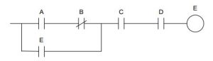
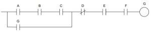
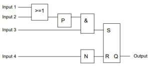
Convert the following to an on-dominant seal circuit:
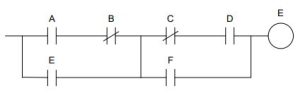
Convert the following seal circuit to a latch/unlatch circuit, to an S/R circuit.
Convert the following seal circuit to a latch/unlatch circuit, to an S/R circuit.
Convert problem 4 to an on-dominant circuit.
Name an action in real-life that requires the unconditional start seal circuit instead of the unconditional stop seal circuit.
Write an on-dominant seal circuit with Input1 on turning the circuit on and Input2 on turning the circuit off.
Write an off-dominant seal circuit with Input1 off turning the circuit on and Input2 on turning the circuit off.
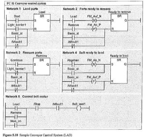
For the Conveyor Belt System, convert to seal circuits. This is a real-world problem from Siemens’ literature in which the program is stated as a written description, I/O list and program. All that is required by this problem is to re-write the rung logic to convert the various rungs from S/R logic to seal circuits. (Ignore one-shots on Reset branch logic.)The following is from a Siemens programming text showing the use of both memory circuits (S/R) and edge trigger or one-shot logic
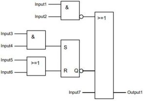
Convert the following to Ladder Logic. First convert to Siemens S/R logic, then A-B seal logic:
Convert the following to Ladder Logic. First convert to Siemens, then A-B.
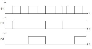
Write the program in the PLC to turn on lights H1 and H2 to satisfy the following timing diagram. By activating switch S1, the light H1 is switched on. If S1 is activated again, a second light H2 becomes switched on. By activating S1 the next time, both lights are switched off. Use one-shot logic to complete. The pattern repeats…
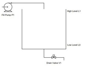
Write the logic in Ladder to satisfy the following control problem. Drain Valve V1 operates independently. When the tank level reaches Low Level L0, turn on Fill Pump P1 to fill the vessel.
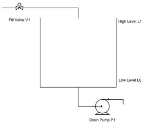
Write the logic in Ladder to satisfy the following control problem. Fill Valve V1 operates independently. When the tank reaches High Level L1, turn on Drain Pump P1 to empty the vessel.
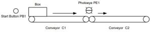
Write the logic in Ladder to satisfy the following control problem:
A box is placed on the first conveyor (C1). Then the operator pulls the pull-cord and the conveyor starts if C2, the second conveyor, is also running. If not, the conveyor C1 waits until C2 starts and then turns on. The box moves on C1 until the trailing edge passes a photo-eye between the two conveyors. Then C1 stops and waits for another box. For this problem, the programmer does not control conveyor C2 but only has a contact from the conveyor C2 reporting its run status.
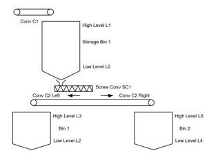
Write the logic in Ladder to satisfy the following control problem:
The process depends on a level switch in the two bins at the bottom (Bin 1 and Bin 2). For either bin to fill, it must be at a low level. Then the conveyor C2 will turn on and Bin 1 or Bin 2 will call for material until the high level is met for the bin being filled. The Screw Conveyor will run delivering material to the conveyor for a fill to either bin. The direction of Conveyor C2 must be correct as well (forward or reverse). Also, Storage Bin 1 has a high and low level switch and will be filled from above by conveyor C1 as needed.
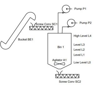
Write the logic in Ladder to satisfy the following control problem:
The main tank will fill with conveyor SC1 and bucket elevator BE1 as well as liquid from pumps P1 and P2. To make a batch, fill to a level with L1. Then fill to a second level with L2. Then turn on the agitator and fill to a final level with L3. When done, agitate for a time and dump using SC2.
Write the logic in Ladder to satisfy the following control problem:
Write the logic to satisfy the following control problem:
The Juice Condenser
Fig. 5-1 The Juice Maker
A description of the above process is as follows:
For saving transportation cost for apple juice, the juice is condensed in a process of evaporation. The water is evaporated in the tank using heat. The process of the process includes the following steps:
Operator pushes the start pushbutton.
Valve V-2 opens and fills to the high level switch and then closes.
Heating occurs with the heat element on and stays on until the level reaches the half level or the temperature rises above 80o C. The temperature switch turns on when the temp reaches 80o C and turns off when the switch falls below 80o C.
Heating is enabled by the high level switch on and the agitator is always on as long as the half level switch is satisfied.
When the half level switch is not satisfied, the condensing process terminates and the tank empties through V-1. After the tank starts emptying, 30 seconds is timed and the tank is assumed to be emptied. The Done/Ready light is turned on and the next cycle is allowed via the Start button.
Read the following description and design a start/stop circuit to satisfy the requirement: (from Dave Perkon, Technical Editor for Control Design who writes the following as a test for those he may interview for a controls job)
“During the interview I simply asked, in writing, that the applicant draw a start/stop circuit ladder diagram using the following hardware: a normally open pushbutton, a normally closed pushbutton, a pilot light and a DPDT relay. I also noted the requirement was to turn on the green pilot light when the momentary start button was pressed and turn off the light when the momentary stop button was pressed. I also asked the applicant to add wire numbers, device designators and relay contact cross references.”
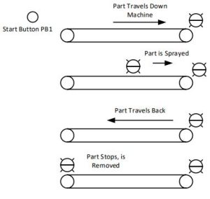
The problem introduced above in Fig. 6-66 moves a part left to right, then back to home. After moving past the center photo-eye, the part is sprayed. The part is sprayed until the part arrives at the right photo-eye at which point the spray turns off and the conveyor reverses direction traveling back to home position at left. Write a program to control the action described.
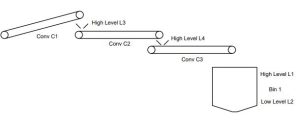
Write the logic in Ladder to satisfy the following control problem:
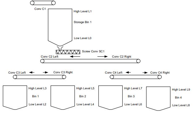
The process depends on a level switch in the four bins at the bottom (Bin 1-4). For any bin to fill, it must be at a low level. Then the conveyor C2 will turn on as well as either C3 or C4 to fill the appropriate bin. The direction of C2, C3 and C4 must be correct as well (forward or reverse). Also, Storage Bin 1 has a high and low level switch and will be filled from above by conveyor C1 as needed.
Next, write the ladder logic to fill any bin that falls below the low level:
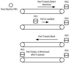
The problem moves a part left to right and into a sanding station. The sander only turns on after PE 2 sees the part. When the part reaches PE 3, the sander turns off and the part returns to the left to PE 1.
Write a program in Ladder to control the action described when the start button is pushed and the system automatically repeats the travel right, then left five times. Include a short time delay at each end of travel.<