2 Ladder Basics
Understanding Electrical Ladder Drawings
Before discussing or understanding the Programmable Logic Controller, we must first understand the devices the PLC was invented to replace. That was the ladder diagram. The ladder diagram or electrical schematic or elementary diagram can be divided into two distinct portions. The first is the power portion and the second is the control. Showing flow of power to a motor or other device in a factory environment is the primary focus of the power portion.
Showing control of that motor is the focus of the control portion. While power flow is important, the focus is to dissect the control portion. Items such as fuses and disconnect devices may appear in both power and control circuits. The use of symbols is important for both power and control. The types of symbols vary and are somewhat arbitrary based on where you are located and, in some cases, the company you work for. This is contrary to the symbols used in the PLC which must be fixed or uniform. The use of symbols is a descriptive description of the device being used. A list of some symbols and the function of the device is given below:
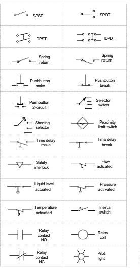
Some of the symbols are used in examples on the following pages. Many devices follow the pattern of how the device actually works. For example, notice how the foot switch resembles an actual foot switch or how a flow or sail switch resembles a sail on a sailboat. Also, note that different combinations of open and closed contacts can be furnished on the same device to give multiple combinations of functions to the control circuit either through hard-wired circuits or to the PLC and then through its logic to the appropriate output.
Many times, the input devices are said to be either normally open (NO) or normally closed (NC). The normally open or closed status refers to the shelf state of the device. If a device is normally open, a resistance check of the device with a digital multi-meter will give a reading of OL. If the device is normally closed, a resistance check will give a reading of 0.0.
The normally open and normally closed state of the devices is not labeled on the ladder drawing. Rather, the reader must recognize the symbol. A helpful hint in trying to determine whether the contacts are open or closed is to think of them in terms of gravity. If gravity is acting on the device, its normal state is as shown in the drawing. An exception to this concept is found in devices that contain springs. For instance, in the drawing of a normally open pushbutton, it appears that the pushbutton should be falling down and closing. However, there is a spring in the pushbutton that holds the contacts in the open (up) position.
Components of the Ladder Diagram
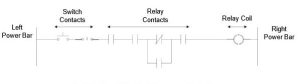
Ladder circuits have some common characteristics. They are:
- Power bar on the far left
- Current flow from the switches combined to allow flow
- One or more relay coils at the right
- Neutral or negative power bar on the right
The following circuit shows a typical ladder rung with switches and relays on the left and the relay on the right:
The control voltage for the system usually is fed from a control transformer that is fed from the power portion of the drawing or from a separate source. It is important to identify the source of power for each circuit. In many instances, more than one source exists and the power may not be off to all circuits when checking a problem with a specific circuit.
Rails usually are protected from over-current conditions with a circuit breaker of fuse.
Ladder drawings may continue from page to page. The rail is shown as continuing from one page to the next usually with an arrow or number with corresponding number on the succeeding page, same position, at the top of the rail feeding the succeeding page.
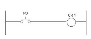
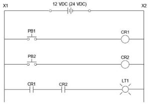
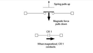
Fig. 2-3 shows a ladder rung. When the pushbutton (PB) is pushed, the circuit is completed and current flows energizing the coil (CR1).
Concerning the placement of devices on a rung, STOP input devices are normally closed devices and are in series on the rung. STOP devices include normally closed pushbuttons, mushroom head buttons, limit switches, or contacts from photocells or proximity switches.
When the STOP, START and other control devices are arranged on the rung, the flow of current to the output may be seen. View the circuit with the objective of determining what is required to turn on the output.
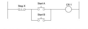
In Fig. 2-4, what must occur to energize the output CR1? The logic developed to turn on the output determines the functions that control the output.
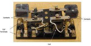
The Relay
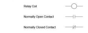
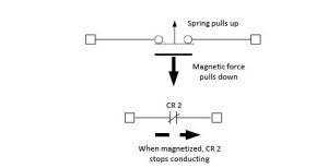
Fig. 2-7 shows the contact arrangement in the relaxed mode for the solid line contacts. The dashed line contacts show the contact arrangement in the energized mode when current is flowing sufficiently through the coil to attract the plunger to contact the steel core inside the coil.
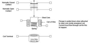
Contacts change as follows when coil energized:
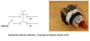
Selector Switches
For selector switches to show continuity in a particular position, x’s and o’s are sometimes used to differentiate which contacts are closed and opened when the switch is in a particular position. The following selector switch is closed in the upper branch, open in the lower branch when in the left position and open in the upper branch, closed in the lower branch when in the right position.
Push buttons come in many sizes and styles. Expect to see examples of the following styles found in various control drawings. They include:
- momentary or maintained contacts
- flush or extended head
- normal or mushroom head
- wobble stick (or joy stick)
- illuminated or non-illuminated
Pilot lights are either push-to-test or standard. Other options include transformer or non-transformer pilot lights. The lens on the pilot light may also be ordered in a number of different colors.
Many push buttons have visible contacts that show the contacts actually closing as the button is pushed. A bar closes between contacts allowing current to flow. The bar that closes the normally open contacts also opens the normally closed contacts.
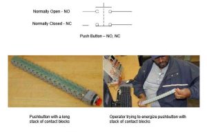
The example of Fig. 2-12 shows a pushbutton with many contact blocks stacked on it. Is this practical? See how hard Eddie must push to energize the pushbutton.
Another device similar to the relay is the timer, pictured below:
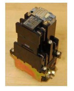
The pneumatic timer is a relay with a dash-pot device attached to the top that delays the change of contact from open to closed or from closed to open for a pre-determined time.
Ladder logic is the logic PLCs were originally invented to emulate. The computer program scanned the inputs and turned on or off relay coils to control machine logic similar to the logic above. The Siemens STL language was a computer language (similar to assembler) capable of solving logic in a manner similar but not as easy to understand by the electrician. Engineers of today must understand both approaches.
Some standards of ladder logic have become standard in the PLC ladder language. A single coil at the right is standard in ladder logic. Power flows from left to right. Contacts either allow or block the flow of power from the left. The PLC as a device emulates these same rules as those allowed in ladder logic found in the control schematic of the 1950’s or 1960’s.
(While flow was from left to right in the US, flow was from top to bottom in European control diagrams. The standard flow in all PLC diagrams is from left to right for LAD diagrams.)
While more than one contact may be combined in series left to right, only one relay may be included in series at the right. More than one coil may be combined in parallel but not in series.
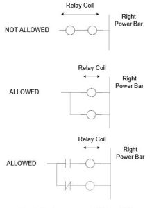
Why does having more than one coil (or light or solenoid) in series not work? Consider voltages in parallel and in series. If voltage is across two devices in parallel, what is the voltage across each? If voltage is across two devices in series, what is the voltage across each?
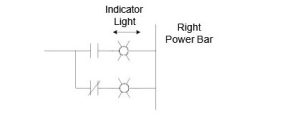
Lights are similar to relay coils and are rated for a particular voltage. They may only be arranged in parallel. Only use one light in series, similar to relays above
A lab at the end of this chapter will go deeper into relay coil and contact implementation as well as logic using the relay.
Boolean Logic
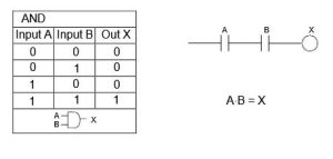
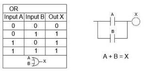
One purpose of relays is to perform Boolean or digital logic. AND, OR, NOT, EXCLUSIVE OR, NOR, and NAND circuits are common in ladder logic and parallel designs found in digital logic circuits. Simple circuits can be combined into larger circuits to perform very complicated tasks. PLCs use the same type of logic as does digital logic texts. Some common digital and ladder logic equivalent circuits follow:
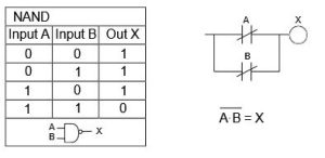
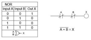
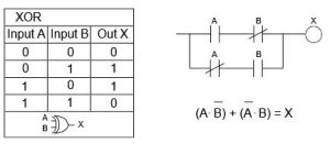
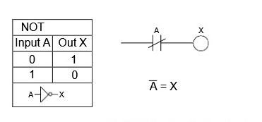
In circuits in which combinations of contacts are used to set bits for control of machines, the relay logic may be broken down into one of the above types of logic.
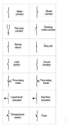
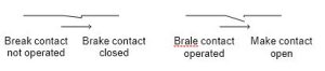
European terminology of the contact is similar to the American normally open or normally closed nomenclature. They are referenced as break and make contacts.
As to the signal transmitters, we differentiate between break contacts and make contacts.
The switch shown below is a make contact; i.e., it is closed exactly when it was operated
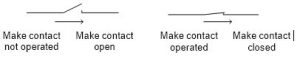
The switch shown below is a break contact; i.e, it is closed exactly when it was not operated.
What do Logic Operations Look Like in the elementary or schematic diagram?
Logic operations are used to specify conditions for switching an output. The European designation of an AND operation is shown below:
A lamp is to light up when two switches are operated simultaneously as make contacts.
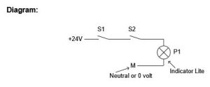
Explanation: The lamp lights up exactly when both switches are operated. That is, when switches S1 and S2 are operated, lamp P1 is lit.
A Discussion of Motor Control Using Ladder Logic
A motor starter is used to start and control a motor. A three-phase squirrel-cage motor is one of the simplest motors to start and control. It is the most used motor in industry. The circuit for starting it is simple as well and resembles a relay circuit similar to the relay seal circuit.
To control a motor, the fuses or circuit breaker as well as overloads and wire for a motor must be sized correctly. From a control point of view, a motor starter circuit is similar to other relay circuits. The power comes from the left and feeds through buttons, switches, and relay contacts to feed a starter (relay) coil. After the starter coil is a set of overload contacts that open if the motor overheats. Overheating is caused by using the motor above its full-load current rating, even if only slightly.
A ladder diagram begins with a power source and neutral usually labeled L1 and L2 (or sometimes X1 and X2). L1 furnishes power and L2 is the neutral. A schematic begins as follows:
In a motor starter circuit, the ladder diagram begins with power supplied from the motor power supply or from an alternate source of power. Usually, power comes from two of the motor leads.
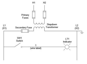
The operating voltage for L1 and L2 may be 120 VAC.
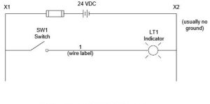
There may also be a DC bus present on a schematic with the power source and ladder displayed as follows:
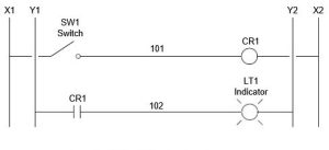
Several ladder busses may be present on the page at the same time, especially an AC bus and a DC bus. They are shown in parallel with the logic from each labeled appropriately. In the following example, a switch at voltage of L1-L2 turns on a relay CR1 which then turns on the light in the X1-X2 circuit. This might be from one AC voltage to another or from an AC voltage to a DC voltage.
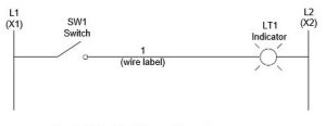
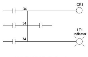
Numbering of wires is also important and each node of a circuit is to be assigned a unique number. Numbers may be assigned sequentially, by line number, by a position in a grid, or by another mutually agreed system between vendor and end user. The example below displays the use of a single node with several branches.
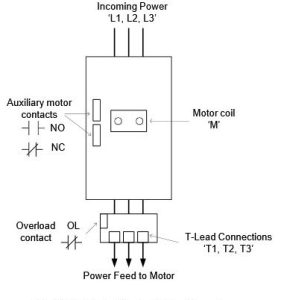
The inclusion of the motor starter circuit in a diagram includes many additional parts to the schematic. They deal with the power portion of the motor starter circuit. The basic circuit for starting a motor is as follows:
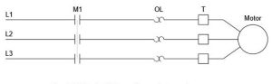
The motor contactor is labeled M1 in this example. The motor contactor is referenced from the coil of the motor starter circuit located in the ladder diagram for the motor. OL refers to the three overload circuits for this motor. Overloads are set to trip at a slightly higher value of current than the full load current of the motor. “T” refers to the T leads, marked T1, T2, and T3, the final termination points prior to the leads for the motor. Then the motor is shown. On most schematic drawings, the motor name and horsepower (HP) rating of the motor are included.
Prior to the motor contactor is a disconnect and either a fuse or circuit breaker. These elements are shown for each line of power L1, L2, and L3. They are shown with a tie element to show that if one of the three overload elements trip, all trip or disconnect.
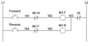
To reverse a three-phase squirrel cage motor, add the following to the motor control circuit:
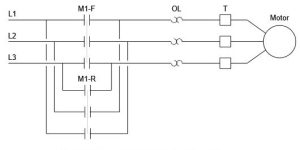
Notice that to reverse a three-phase motor, switch any two leads to the motor. The motor starter must guarantee that both M1-R and M1-F are not turned on at the same time. If this happens, the contactors will short and a fuse will blow or the circuit breaker will trip. A motor circuit could be designed to start one contactor only as follows:
The design can incorporate the seal circuit found in Lab 2.1. To incorporate the seal circuit, a holding contact must be used around the start push button for each the forward and reverse motor circuits.

Forward-Reverse motor starter circuits use a mechanical toggle bar so both contactors cannot be energized simultaneously. This provides a mechanical fail-safe to the electrical circuit in Fig. 2- 26 and 2-27.
While electrical students may never be required to actually wire a motor starter to control a motor, the experience of wiring a motor starter control circuit is of value. Wiring and debugging 120 VAC logic provides a greater challenge because of the higher possibility of electrical shock. Care must be taken to wire the circuit with no short-circuits in it. Troubleshooting of the circuit must only be done with the power off in a laboratory environment. It is acknowledged that most applications in the manufacturing environment are checked with the power on (the circuit is hot). Various types of automatic and manual control circuits can be designed to start the motor circuit.
For example, the Auto/Manual selector switch is available to allow the end user to choose which mode is to be used when running the motor. It is constructed as follows:
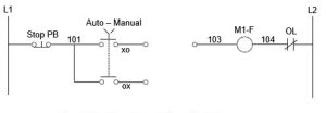
The Auto/Manual switch allows the user to choose a path for control. The xo and ox nomenclature is a handy means of labeling the position of the switch for which the contact is closed. For example, in Fig. 2-28, the upper path is closed when the switch is in Auto and the lower path is closed in Manual.
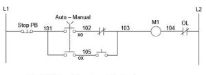
The following schematic shows a possible design using the Auto/Manual selector switch. In automatic, the motor circuit responds when the relay contact turns off while in manual, the motor turns on when the push button is energized.
Multiple position switches, push buttons and other control contacts may be inserted to control the more complex motor circuit. Example circuits shown below are indicative of the kind of circuits designed in industry.
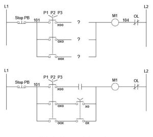
To design a motor starter circuit, it must be decided whether or not a memory circuit is to be used. If the motor contactor provides the memory circuit, then use a circuit similar to Fig. 2-22 with a seal for each direction of motor operation. If a jog switch is used, no seal circuit is required since the jog switch implies holding the button down to move the motor. Later, a jog switch is incorporated into a memory circuit to allow either the motor to be started and stopped or jogged. Switches are used to choose modes of operation and separate one mode from another.
Wiring the starter:
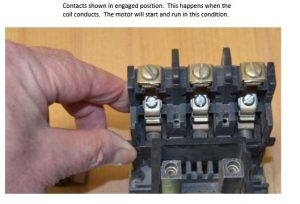
Three phase contactors have three contacts that simultaneously close to start the motor and open to stop the motor. To reverse the motor, the opposite contactor must be guaranteed to be open (checked mechanically and electrically) and any two of the three leads are reversed for reverse operation of the motor.
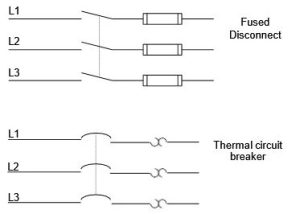
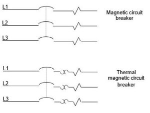
Motor contactors are part of an overall control circuit to guarantee that the motor is protected from burning up and that the wire is protected from short circuit conditions. Ahead of the motor starter contactor is found a set of three fuses or a circuit breaker capable of interrupting the current from a fault in the motor, the wiring or any part of the circuit downstream from the circuit breaker. Usually fuses are used since they tend to be cheaper. Fuses are also used due to their overall high fault interrupting ratings. Circuit breakers are chosen when it is critical that circuits be reset quickly and downtime searching for a replacement fuse is unacceptable. Circuit breakers are also used since fuses may allow a motor to burn up if a single fuse blows and the motor runs for a short while on a single phase. Overall fault current must be checked when selecting a circuit breaker for motor starting applications, however.
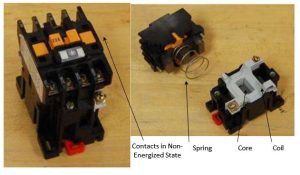
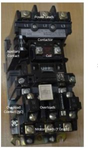
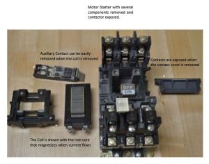
Overloads are used to protect the motor from low over-current conditions. The overloads are set to trip at a current rating slightly higher than the full load current of the motor. Overloads are calibrated to not trip with a rise in the ambient temperature but with a rise in the current of the motor creating additional heat in the overload relay. In the figure below, an Allen-Bradley motor starter is shown. Labels indicate the various parts of the starter.
The following diagram shows the major components of a Motor Starter:
Aside from NEC
The National Electrical Code is not the focus of this chapter but should be read by every electrical student before entering the work force. This book deals with proper and safe installation of electrical equipment. Included are rules for installation and design as well as tables for design of electrical equipment. For example, Chapter 9 includes Table 8 defining the ohms per foot rating for different wire size.
The table lists various AWG (American Wire Gage) size wire, both solid and stranded and the ratings in ohms/km. Some are listed below:
- #14 stranded 10.3 ohm/km
- #12 stranded 6.50 ohm/km
- #10 stranded 4.070 ohm/km
- #8 stranded 2.551 ohm/km
Converted to ohm/ft,
- #14 stranded 3.1212E-3 ohm/ft
- #12 stranded 1.9697E-3 ohm/ft
- #10 stranded 1.233E-3 ohm/ft
- #8 stranded 7.730E-4 ohm/ft
Example Using NEC for Electrical Calculations
Use these values to calculate the voltage drop in the various wire choices for 1Amp. If the voltage drop is to be less than 10 V., then
10V = 1 A x ohm/ft x (number of ft)
For a 5 A load, the formula changes to:
10V = 5A x ohm/ft x (number of ft)
Note that if the circuit is 110 V and single phase, the length out and back to a device must be included.
For example, if a solenoid is capable of turning on with an inrush of 5 A and has a holding current of .2 A, what is the maximum length that #14 stranded may be used for a voltage drop of 10 V.
Answer: 10V=5.0 x 3.1212E-3 x Ft Ft = 641.76 total or apx. 320 ft to the device