6 Basic Memory Circuits
In this chapter, we take a look at the memory circuits used in programs in the US and in Europe. There are differences. The Allen-Bradley programming language definitely encourages the use of seal circuits while Siemens’ programming allows the Set/Reset circuit or the seal circuit. Both will be discussed in depth and their use in programming applications follow. Also, this chapter introduces the one-shot or edge trigger. It is a highly used addition to most circuits and its use should be well understood.
The memory circuit, while either the US or the European type, is the basic building block for all programs involving automation and control of a process. Its use is foundational to all logic that follows. In Ch. 7, we discuss the memory circuit (seal circuit) with a timer. In Ch. 8, we discuss the memory circuit with comparison statements. Ch. 8 also introduces the idea of numbers instead of bits to set memory steps or states. Ch. 11 introduces the concept of states and discusses various ways of programming them. The first method proposed in most state diagrams is the use of the basic memory circuit (either seal or S/R). Later chapters use the memory circuit to build a foundation for control of a particular process – either batching (Ch. 13), mode (Ch 15), motion (Ch. 17) or PID (Ch. 19).
After a discussion of the one-shot and introduction of some simple one-shot circuits, we discuss some early design of memory circuits. These examples form the foundation for more sophisticated applications in later chapters.
Developing the Memory Circuit
We look first at a very simple system. This circuit gives a look at how memory circuits have been a part of digital logic and how the digital concepts have links to the Ladder diagram circuits used later in the chapter.
The Acme Company has a problem flow of molasses in a storage tank. In the winter, viscosity of the molasses is so high that the molasses run too slow to exit the flow valve. A present system allows for flow out of the tank on request but no sensing of temperature. A second model is to be put in place to allow for a heater to be turned on while the molasses are cool and then flow out of the valve.
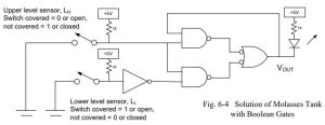
The first model does not have a temperature sensor or heater. Sensors consist of two level sensors, LH, and LL. The tank outlet valve turns on to empty the tank when the upper level is reached. After opening, the outlet valve was closed when only when LL has been reached.
The system as designed is shown below.
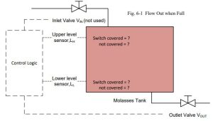
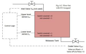
Signal assignment must be made of the level switches LH and LL. These switches must be assigned a value of 1 or 0 when the switch is covered (level exceeds the switch). A switch must be assigned a value that is safe, that is, that limits bad consequences if the switch fails. The most likely fault is for the switch to lose a wire (wire fall off and open the circuit). If this happens, would the circuit allow some bad event to occur? In the event of LH, the switch is used to stop the fill sequence (turn off the circuit). It is proper to think of switches that stop a memory circuit as the same as a stop switch. Stop switches are assigned the value 0 when the switch level is exceeded. For the switch LH, the switch covered = 0, switch not covered = 1. Not all switches are as easy to assess and in some cases, either 0 or 1 is proper to assign as the value for “Signal Assignment”.
In addition to finding a truth table and Karnaugh map, the requirement for safety requires a signal assignment table:
| Sensor | Function/State | Signal Assignment |
| LH | Upper Level | 0 |
| LL | Lower Level | 1 |
Table 6-1a Input Assignment
| Actuator | Function/State | Signal Assignment |
| VOUT | Outlet Valve | 1 |
Table 6-1b Output Assignment
The Signal Assignment can be assigned to the Molasses Tank and filled in on the system diagram:
A Truth Table is designed and a Karnaugh map is developed from it: Truth table for outlet valve VOUT
| LH | LL | VOUT | VOUT | Action |
| 0 | 0 | 0 | 0 | Sensor error; open valve |
| 0 | 0 | 1 | 0 | Sensor error; open valve |
| 0 | 1 | 0 | 1 | Both sensors covered; open valve |
| 0 | 1 | 1 | 1 | Both sensors covered; maintain open valve |
| 1 | 0 | 0 | 0 | Level below low; leave valve closed |
| 1 | 0 | 1 | 0 | Level below low; close valve |
| 1 | 1 | 0 | 0 | Level between low, high; maintain open |
| 1 | 1 | 1 | 1 | Level between low, high; maintain closed |
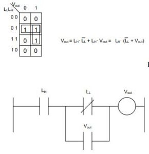
The Karnaugh Map Simplification of Vout, Boolean Equation, Ladder Equivalent is developed. The final design circuit could be built from logic gates and demonstrated for a lab experiment. The addition of circuits for temperature and alarm could be added as well. This may be all that is required in the academic world. In the real world, however, a PLC or similar device is employed to turn on and off devices and report the result to computer systems monitoring the factory’s production. This requires more effort than the simple circuit design found on the next page.
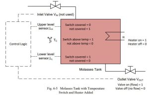
System modifications to the molasses tank include a temperature sensor, Tc and heater H. Level sensors, LL and LH, are retained.
The outputs are one valve, VOUT, an alarm, A, and a heater, H. The heater must warm the molasses enough for proper flow.
When the upper level sensor is covered, the outlet valve should open if temperature is sufficient for proper flow. Flow should be allowed until the lower sensor is reached or temperature falls below the minimum temp for good flow. Once flow stops, the outlet valve closes until the upper level switch is again covered. Alarms will show improper combinations of level switches.
Alarms will also cause flow to stop and heater to turn off. The heater is off if the low level switch is not covered.
| Sensor | Function/State | Signal Assignment |
| LH | Upper Level | 0 |
| LL | Lower Level | 1 |
| TC | Temperature Sw | 1 |
| Actuator | Function/State | Signal Assignment |
| VOUT | Outlet Valve | 1 |
| A | Alarm | 1 |
| h | Heater | 1 |
Truth table Revised System:
| LH | LL | TC | VOUT | VOUT | H | A |
| 0 | 0 | 0 | 0 | 0 | 0 | 1 |
| 0 | 0 | 0 | 1 | 0 | 0 | 1 |
| 0 | 0 | 1 | 0 | 0 | 0 | 1 |
| 0 | 0 | 1 | 1 | 0 | 0 | 1 |
| 0 | 1 | 0 | 0 | 1 | 1 | 0 |
| 0 | 1 | 0 | 1 | 1 | 1 | 0 |
| 0 | 1 | 1 | 0 | 1 | 1 | 0 |
| 0 | 1 | 1 | 1 | 1 | 1 | 0 |
| 1 | 0 | 0 | 0 | 0 | 0 | 0 |
| 1 | 0 | 0 | 1 | 0 | 0 | 0 |
| 1 | 0 | 1 | 0 | 0 | 0 | 0 |
| 1 | 0 | 1 | 1 | 0 | 0 | 0 |
| 1 | 1 | 0 | 0 | 0 | 1 | 0 |
| 1 | 1 | 0 | 1 | 0 | 1 | 0 |
| 1 | 1 | 1 | 0 | 0 | 1 | 0 |
| 1 | 1 | 1 | 1 | 1 | 1 | 0 |
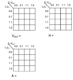
Students should finish the Karnaugh Maps, Boolean Equations and Ladder equivalent. This control circuit may be the needed outcome of the control algorithm. It may not be the best algorithm, however. The engineer/program designer may first try such a circuit and find it to be lacking. In this case, if the temperature switch is never satisfied, the output valve VOUT is never energized. While this may be the desired result, there may be a better approach that should be looked into. In the meantime, realize that you may have “the best possible program” and find
that in the activation/startup phase that it may need to be totally revamped to satisfy the “real” problem with the machine or process. The program engineer must also be careful to not create conditions that would cause equipment failure such as a solenoid cycling on and off continuously. While an electronic device may survive for years constantly cycling on and off, a mechanical device such as a solenoid will not stand up to such abuse and quickly burn up.
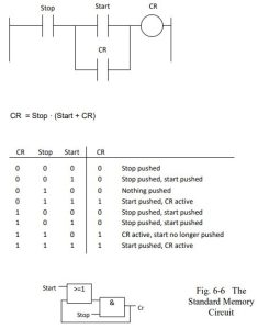
In general, memory circuits resemble the following and the Truth Table/Karnaugh Map step may be skipped:
Relay Instructions/Memory Instructions
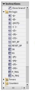
Instructions for building memory circuits in Ladder and FBD are discussed next. They include instructions commonly referred to as ‘Bit’ logic instructions. Siemens and Allen-Bradley each provide a number of instructions capable of building combinational and memory circuits. While the same instructions may not be referenced by the same name, the function of the Normally Open and Normally Closed contact for both A-B and Siemens produces the same result.
Differences arise when using some of the other instructions, however. The main difference between the two is the path most programmers take as a first choice when programming their respective PLC. The European style of programming will be discussed as varying somewhat from the American style.
Review of class of instructions for bit logic for Siemens and Allen-Bradley are listed below: Siemens instructions for Bit logic are:
Allen-Bradley instructions for Bit logic are:

Normally Open Contact
Siemens Step 7 Basic:
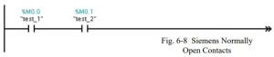
The two contacts form an ‘and’ of the two points, “test_1 and test_2”. If both signals have the signal state “1”, the combination will conduct from the left power rail to the right. Otherwise, if either input does not have a “1” state, power is not passed. Siemens refers to the contact as a normally open contact, the traditional name associated with controls drawings.
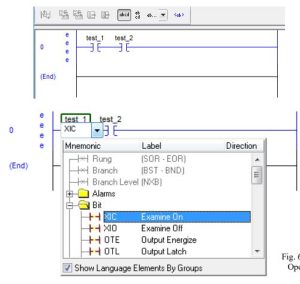
Allen-Bradley refers to the normally open input as an XIC or “Examine On” contact. The RSLogix 5000 example below uses the same two inputs “test_1 and test_2”. Internal memory addresses are assigned tag addresses with BOOL data type.
Contacts can be arranged either in ‘and’ or ‘or’ arrangements starting at the left power rail and flowing to the right. Contacts must be placed on horizontal runs and never on a vertical run.
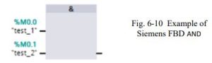
The expression above would be written in Boolean: test_1 and test_2 =
and the FBD diagram would be:
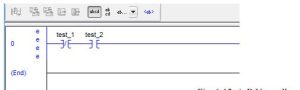
Normally Closed Contact
Siemens Step 7 Basic:
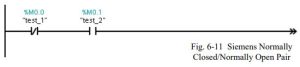
The two contacts form an ‘and’ of the two points, “not test_1 and test_2”. If test_1 is 0 and test_2 is 1, the combination will conduct from the left power rail to the right. Otherwise, power is not passed. Siemens refers to the first contact as a normally closed contact, the traditional name associated with controls drawings. The second contact is a normally open contact.
Allen-Bradley refers to the normally closed input as an XIO or “Examine Off” contact. The RSLogix 5000 example below uses the same two inputs “not test_1 and test_2.
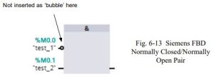
The normally closed contact provides the same function as the “NOT” function of Boolean logic. The expression above would be written in Boolean: not test_1 and test_2 =
and the FBD diagram would be:
Invert Result of Logic Operation
Siemens Step 7 Basic:
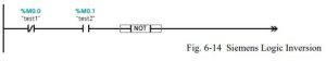
The Invert instruction will invert the state at the point of inclusion. If the state at the point was “1”, the output of the Invert [NOT] instruction is “0”. Likewise, if the state at the point was “0”, the output of the Invert [NOT] is “1”.
The instruction has many practical uses in logic design. No instruction is available in the Allen- Bradley instruction set that exactly duplicates this instruction from Siemens.
The instruction above is read “not[not test_1 and test_2]” and the FBD diagram would be:

Output Coil
Siemens Step 7 Basic:
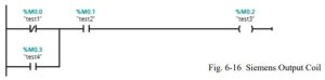
The output coil bit sets a bit of memory for a Boolean logic expression. It adds the resultant to the equation. Before, the result was not included in the equation but with the coil, an output is set to 0 or 1.
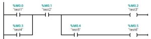
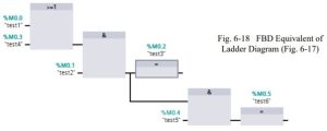
Multiple coils may be programmed but this is not necessary. Multiple coils with additional logic may be programmed and this may be necessary. Use of multiple coils in one network is shown below. The FBD equivalent is also shown.
The following shows the FBD equivalent of the Ladder circuit above.
The following is the Allen-Bradley equivalent of the Siemens Ladder and FBD circuit.

Negated Coil
Siemens Step 7 Basic:
The Negated Coil inverts the logic of the network and assigns the inverted signal value to the tag. Siemens uses the term RLO to signify the signal value at a point in the circuit. RLO is short for Result of Logic Operation and signifies the status of the network at the point investigated. In the case of the Negated Coil, the RLO is inverted to find the status of the negated coil.
No instruction is available in the Allen-Bradley instruction set that exactly duplicates this instruction from Siemens.
Set Output
Siemens Step 7 Basic:
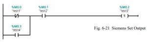
The Set Output operation sets the state of the Boolean bit to 1. If power flows to the output bit, the output bit is set. If the result is 0, the output remains unchanged (may be 0 or 1).
Reset Output
Siemens Step 7 Basic:
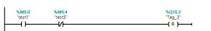
The Reset Output operation sets the state of the Boolean bit to 0. If power flows to the output bit, the bit is reset (to 0). If the result is 0, the output remains unchanged (may be 0 or 1).
Set_BF Output
Siemens Step 7 Basic:
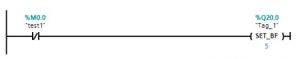
The Set_BF instruction sets several bits beginning at the stored address. The number of bits set is defined in the second operand . As seen in the example above, 5 bits starting at Q20.0 are set with the instruction if power flows to the output.
Reset_BF Output
Siemens Step 7 Basic:

The Reset_BF instruction resets several bits beginning at the stored address. The number of bits reset is defined in the second operand . As seen in the example above, 4 bits starting at Q20.0 are reset or turned off with the instruction if power flows to the output.
SR: Set reset flip-flop
Siemens Step 7 Basic:
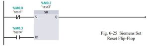
The SR flip-flop is used to set or reset a specific output operand based on the state of the S and the R inputs. The Reset or R input dominates. If the S is 1 and the R is 0, the output turns on – 1. If the S is 1 and the R is 1, the output turns off – 0. If the S is 0 and R is 1, the output turns off.
RS: Reset set flip-flop
Siemens Step 7 Basic:
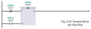
The RS flip-flop is used to set or reset a specific output operand based on the state of the S and the R inputs. The Set or S input dominates. If the S is 1 and the R is 0, the output turns on 1. If the S is 1 and the R is 1, the output turns on – 1. If the S is 0 and R is 1, the output turns off – 0.
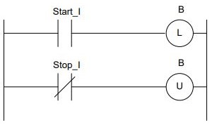
OTL: Output Latch
These instructions are Allen-Bradley instructions similar to the SR or RS flip-flop instructions of Siemens. The orientation determines the dominance. If (L) is before (U), the Unlatch or Reset is dominant. If (U) is before (L), the Latch or Set is dominant. The difference between A-B and Siemens is that the bit programmed for the latch is retained after a power fail or change to program mode and then back to run. The Siemens data bit will turn off after a power fail or change to program mode and then back to run. Certain data areas in the Siemens program are reserved for data that is retained and can be programmed using the S-R flip flop similarly to the A-B latch.
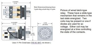
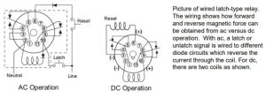
The circuit and its mechanical description are shown above. The latch relay is maintains in its last position even though power may not be present. The Allen-Bradley instruction for latch and unlatch is an exact representation of this mechanical device. The Siemens S-R relay may be the same or may be a coil that is reset to 0 if the power is removed. To determine whether the S-R coil is retentive is determined by the address location of the coil in the M table.
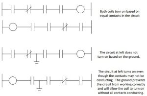
Why Coils are Located to the Right
Why is the Coil located right of the contacts in general? The tradition has roots in the relay logic before PLCs were implemented. The following two circuits show the difference. If a ground occurs in the circuit, the relay at right will not turn on while at left, it probably will. This may cause errors in circuit function.
Retentive Memory
Retentive refers to the coil’s ability to retain its former status through a power loss. If the PLC either loses power or stops processing the program, coils are reset to 0 unless specified as a latch coil. Latch coils retain their state when the power is turned back on or when the program returns to the run mode. Mechanical relays accomplish this with a slide-over arrangement similar to the light switch on the wall. The coil’s status remains in the last state until energized to move to the opposite state.
Problems inherent in latch coil design cause their use to be restricted to applications requiring their use. For example, it is difficult to determine the state of a coil if both the latch and unlatch coil are on at the same time. A mechanical relay will hum and eventually burn up because high inrush currents would continue to flow if the relay’s air gap is not essentially zero distance between the core and plunger. Although the program can determine which rung will be dominant (either latch-L or unlatch-U), the condition is generally not considered good programming practice and something to guard against.
Also, the programmer must guard against all conditions that may cause the circuit to reset the latch coil to off and provide for those conditions with the Unlatch coil. Many circuits do not provide for all conditions to reset the coil.
Seal circuits are developed differently than latch coils. In seal circuits start logic is positive and stop logic is negative for relay coils. In Latch coils (L), the logic is positive that turns on the coil. In Unlatch coils (U), the logic is also positive that turns off the same coil. Coils allow the end user to cycle power and de-energize all seal circuits. This ability to cycle power and restart a machine from a known state is very useful and should be used as much as possible. If the program does not follow this suggestion, the result may be a flurry of mid-night calls to fix the machine. Machines that use latch circuits in them are sometimes described as machines that have “a mind of their own” since all circuits may not be reset to a known state with a power reset.
From Instruction Help, Allen-Bradley describes the Latch function as:
“This instruction functions much the same as the OTE with the exception that once a bit is set with an OTL, it is “latched” on. Once an OTL bit has been set “on” (1 in the memory) it will remain “on” even if the rung condition goes false. The bit must be reset with an OTU instruction.
Latch and Unlatch instructions must be assigned the same address in your logic program. Output addresses are specified to the bit level.
Conversion of control circuitry to PLC logic requires care to correctly represent the circnit’s original design. Use of latch-unlatch coils or S-R flip-flop circuits with retentive memory is to be limited to only circuitry with a need for retaining a previous state.
Stepping Through Various Memory Designs
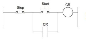
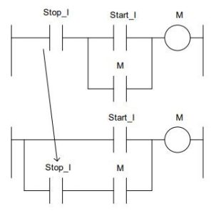
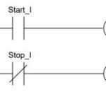
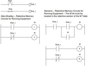
The following circuits demonstrate a PLC emulating the seal control circuit of an off-dominant memory circuit (Fig 6-31b) and on-dominant memory circuit (Fig 6-31c). In an off-dominant circuit, the STOP is dominant. The START button only will work if the STOP button is not pushed. The second circuit re-arranges the circuit to allow the START to work regardless of the position of the STOP. This is referred to as an on-dominant circuit. In general the off-dominant circuit is preferred as it is safer.
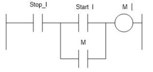
Both types of rungs are found in logic. Typically, the first or off-dominant is found in most logic but the latter or on-dominant is used from time to time. To convert from an off-dominant to the on-dominant, move the stop contact to the seal loop.
Siemens provides the S-R flip-flop circuitry to provide the same seal circuit shown above.
Circuits with off-dominant structure are used in most control circuits while the on-dominant structure is used in alarm circuits (circuits that report something bad). While no absolute rule exists, an alarm circuit will almost always use on-dominant and control circuits will use off- dominant.
On-Dominant:
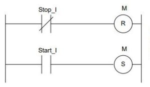
Off Dominant:

As long as the circuit is started or stopped with a single contact, it is simple to design. Most circuits do not just have one start or stop contact, however.
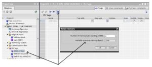
The figure 6-33e shows the method used to set retentive memory in the Siemens’ S7-1200 processor. The retentive byte threshold starts at MB0 and is set to 0 signifying no retentive memory is reserved in the program. If this number is incremented above zero, then the threshold of retentive memory is set at this new boundary with the memory below reserved as retentive while the memory above the threshold as non-retentive. The total number of bytes is limited in the 1214C processor to 2048. While this is somewhat restrictive, the limit has been raised in later processors to a much higher memory limit.
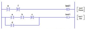
An Exercise Converting Between Seal and Latch/Flip-Flop Logic
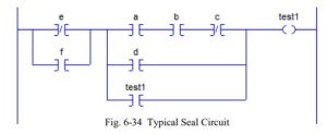
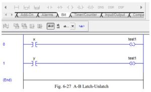
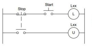
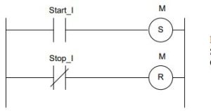
The circuit above is a seal circuit with the start portion in parallel to the test1 contact and the stop portion in series with the test1 contact. The start portion is moved intact to the latch coil. The stop portion is negated (DeMorgan) and moved intact to the unlatch coil.
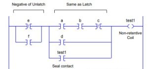
The following is the latch/unlatch equivalent of the circuit above:
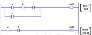
The same circuit could be used for Siemens’ S-R flip-flop. These are Off-dominant circuits.
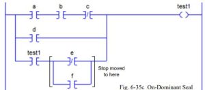
To convert to the On-dominant circuits, move the Stop portion of the circuit to in series with the seal contact.
To convert to the On-Dominant Latch circuit, switch the position of the L and U coils. The Latch or on portion now dominates. Siemens’ R-S flip-flop has similar results.
While European and American programmers tend to have their preferences for memory circuits, we should be ready to convert from one style to another as necessary. In general, American- trained engineers tend to use seal circuit design and European-trained engineers tend to use S-R circuit design as well as a now-antiquated assembler look-alike language Statement List (STL).
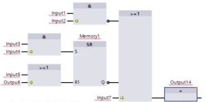
Other memory circuits are shown below. They show the implementation of memory circuits in FBD as well as Ladder circuits. FBD is more able to combine complicated memory circuits into one circuit as shown below:
Logical operations including memory embedded in the circuit :
To review, for non-retentive circuits, the Allen-Bradley memory circuit is shown on the left and the Siemens’ on the right. They are:
(Alarm and Reset contacts are Normally Open contacts.)
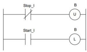
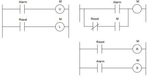
To review, for retentive circuits, the Allen-Bradley memory circuit is shown on the left and the Siemens’ on the right. They are:
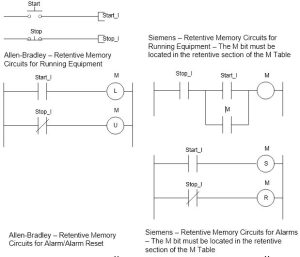
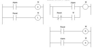
(Alarm and Reset contacts are Normally Open contacts.)
Use of Seal (Memory) Circuits
The following example shows the need for a seal or memory circuit.
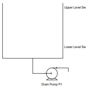
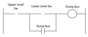
A tank is filling from above from buckets of water dumped into the tank. When the tank’s upper level is reached, the pump starts and empties the tank until the lower level switch is reached. At this time, the pump turns off. The program of the pump starter circuit is found after the Function/State table on the next page.
Solution:
The correct contact must be identified as the start contact and as the stop contact. For instance, when a pump is installed above the tank to fill the tank, the lower level switch becomes the start contact and the upper level switch becomes the stop contact.
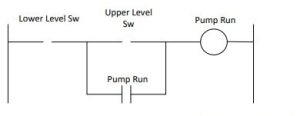
The circuit below demonstrates the principle of a seal or memory circuit used to fill a vessel.

| Sensor | Function/State | Signal Assignment |
| LH | Upper Level | |
| LL | Lower Level |
| Actuator | Function/State | Signal Assignment |
| Pump | Pump liquid in | 1 |
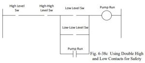
Many times, two contacts are used to back up critical applications. In this case, both are used in the start or stop circuit with the second or back-up contact also used to alarm. For instance, the following circuit would be controlled as before except that an additional contact is found to also start or stop the circuit. In addition to the control portion of the control circuit, a diagnostic or alarm circuit is also used with the Hi-Hi and Low-Low contacts to alert the operator or supervisor that a problem has occurred.
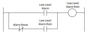
Use of Alarms – On-Dominant Seal Circuits
An alarm is programmed to turn on when the alarm is detected and not turn off until an acknowledgement is received. The following circuit shows how this circuit can be built:
One-Shot Logic
One shot or positive signal edge instructions predate both the Siemens and Allen-Bradley current processors. The first believed to introduce the concept was Modicon with the Modicon 484 processor in 1978. Their positive transition and negative transition instructions were unique and added to the computer flavor of the PLC over the idea of just a relay replacer. The instructions were:
The Modicon 484 instructions did not require the use of a blocking bit as both the Siemens and A-B processors do. Instead, Modicon kept a complete last-scan table of the entire Boolean table of inputs, outputs and discrete internal bits used in logic. This last-scan table then was used to report on the previous scan’s status. If the status was different than the present scan, then a signal was allowed to pass. Otherwise, the branch was effectively blocked from passing power. While an excellent concept, the execution time needed to process this function was prohibitive time-wise and was dropped with subsequent manufacturers implementing the one-shot instruction. Both Siemens and Allen-Bradley use a blocking bit that is programmed to keep the last-scan information at hand and process an instruction similar to the Modicon approach. They both require this blocking bit be programmed and defined, however. The blocking bit is not used in logic. It is only used to block the future scans of power through the branch. You may say that you have to use a bit (blocking bit) to get a bit (one-shot bit). This may help you as you work through this next section.
Again, the definitions below are from the ‘help’ screen from the TIA portal. A more complete definition for these instructions may be found in the Siemens Reference Manual.
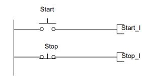
Edge Detection- Siemens
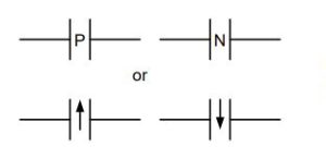
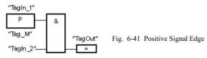
|P|: Scan operand for positive signal edge
“The ‘Scan operand for positive signal edge’ instruction is used to determine whether there is a 0 to 1 change in the signal state of a specified operand (). The instruction compares the current signal state of the operand with the signal state of the previous query saved in an edge memory bit (). If the instruction detects a change in the result of logic operation from 0 to 1, there is a positive, rising edge.
If a falling edge is detected, the output of the instruction has the signal state 1. In all other cases, the signal state at the output of the instruction is 0.”
The following example shows how the “Scan operand for positive signal edge” instruction works:
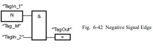
|N|: Scan operand for negative signal edge
“The ‘Scan operand for negative signal edge’ instruction is used to determine whether there is a 1 to 0 change in the signal state of a specified operand (). The instruction compares the current signal state of the operand with the signal state of the previous query saved in an edge memory bit (). If the instruction detects a change in the result of logic operation from 1 to 0, there is a negative, falling edge.
If a falling edge is detected, the output of the instruction has the signal state 1. In all other cases, the signal state at the output of the instruction is 0.”
The following example shows how the “Scan operand for negative signal edge” instruction works:
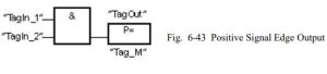
(P=): Set operand on positive signal edge
“The ‘Set operand on positive signal edge’ instruction is used to set a specified operand () when there is a 0 to 1 change in the result of logic operation (RLO). The instruction compares the current result of logic operation with the result of logic operation from the previous query, which is saved in the edge memory bit (). If the instruction detects a change in the RLO from 0 to 1, there is a positive, rising edge.
When a positive edge is detected, is set to signal state 1 for one program cycle. In all other cases, the operand has the signal state 0.”
The following example shows the parameters of the “Set operand on positive signal edge” instruction:
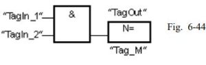
(N=): Set operand on negative signal edge
“The ‘Set operand on negative signal edge’ instruction is used to set a specified operand () when there is a 1 to 0 change in the result of logic operation (RLO). The instruction compares the current RLO with the RLO from the previous query, which is saved in the edge memory bit (). If the instruction detects a change in the RLO from 1 to 0, there is a negative, falling edge.
When a negative edge is detected, is set to signal state 1 for one program cycle. In all other cases, the operand has the signal state 0.”
The following example shows the mode of operation of the “Set operand on negative signal edge” instruction:
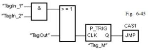
P_TRIG: Scan RLO for positive signal edge
“The ‘Scan RLO for positive signal edge’ instruction is used to query a 0 to 1 change in the signal state of the result of logic operation (RLO). The instruction compares the current signal state of the RLO with the signal state of the previous query, which is saved in an edge memory bit (). If the instruction detects a change in the RLO from 0 to 1, there is a positive, rising edge.
If a rising edge is detected, the output of the instruction has the signal state 1. In all other cases, the signal state at the output of the instruction is 0.”
The following example shows how the instruction works:
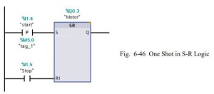
The following is an example from Siemens showing one-shots in S-R logic:
Edge Trigger or One-Shots in A-B Instructions
Allen-Bradley refers to the edge trigger instructions above as One Shot instructions. To use one- shot logic, a circuit similar to the following must be programmed for the SLC processor.
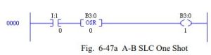
This circuit responds as follows:
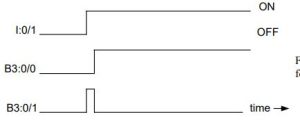
Notice that the desired coil to be used in the program is the coil at the right. The OSR bit is used as a blocking bit and is not as a rule referenced elsewhere in the program. The OSR bit may be useful if the input I:0/1 is necessary one scan delayed. Otherwise, it is not to be used in any other logic in the program. B3:0/1 is on for only one scan. This may be very short as in a millisecond or less or in the slower PLCs, the delay may be 20, 30, or even 50 milliseconds. It is a relatively quick transition, however, and is not seen on the screen of the monitoring program in most circumstances.
The OSR is used as a conditional input triggering an event only on the leading edge. Use the OSR command to start a sequence of events when an event occurs. A one-shot in electronic terms squares a waveform and makes it more exact for the circuitry. The PLC one-shot is primarily equal to the electronic one-shot in that it runs through the entire program one time with an on pulse and then turns off.
The OSR is to be placed immediately before the output instruction. It is referenced with a bit that is not used elsewhere in the program. Either a binary file or integer file address may be used.
An example of improper use of the OSR command for the MicroLogix 1000 processor is shown below when a parallel branch is programmed around the [OSR] instruction.
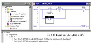
To correct the problem in the circuit, all parallel branches must be resolved before the [OSR] instruction as shown below:
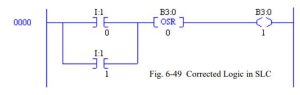
The ONS instruction turns the output of the rung to on for one scan when the contact sees a false- to-true transition of the conditions preceding the ONS instruction on the rung. Rules for the Micro1200/1500 ONS one-shot are similar to other SLC processors’ OSR instruction. Rules for these one-shot instructions include:
- Never branch around the OSR or ONS instruction
- Use the OSR or ONS instruction to turn on an output
- Other contacts may exist between the OSR or ONS instruction and the output coil
The OSR commands are used by the MicroLogix 1200 and 1500 as output coils and are one-shot bits used on the rising or falling of power to the output. An example of an OSR instruction used in RSLogix 5000 programs is shown below:
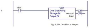
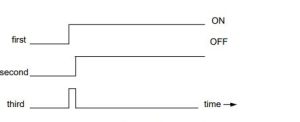
The OSR circuit above acts in a similar manner to the ONS instruction with tag names instead of file names used in the SLC architecture. The timing diagram for the OSR above is shown below:
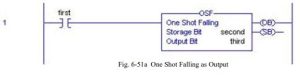
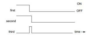
Similar to the OSR instruction is the OSF or One Shot Falling bit. Its timing chart is shown after the instruction:
A more robust type of one-shot is the ONS one-shot found in the MicroLogix 1200, 1500 and ControlLogix/CompactLogix processors. The purpose of this newer type is to provide one-shot logic inside a single rung without having to create a rung for the one-shot and then a second rung that includes the one-shot logic.
In this example, the [ONS] instruction acts as a blocking bit one scan delayed. The resulting logic creates a one-shot signal in the branch of the [ONS] instruction. An example of the use of the [ONS] instruction is shown in addition to the circuit’s timing diagram:
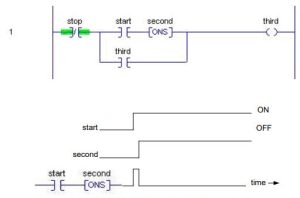
The series branch of start and [ONS] combine to provide a one-shot when start turns on. The input start may remain on for a long duration but the branch of the network will remain on for only one scan.
Use of the One Shot
The use of one-shot contacts requires programmers to ask when the leading edge of a signal is more useful in the development of logic than the signal itself. Experience is the best teacher in knowing when to use the one-shot.
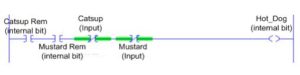
For an example of a one-shot that can occur without the need to build an [ONS] or [OSR] instruction, refer to Lab 4.1, The Hot Dog Counter.
In the logic of the Hot Dog Counter, the rung output turns on incrementing the counter. Then the program starts again at rung 0 executing the first two rungs. These two rungs turn off, in turn turning off the count bit. The count bit is only on for one scan. The count bit (Hot_Dog) is essentially a one-shot coil that turns on for one scan only before turning off.
Example of Making Momentary Switch into Toggle Switch
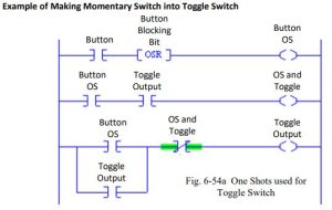
The circuit above is useful to turn a pushbutton input into a toggle-type switch. The use of one- shot logic is of benefit. Each time the input Button turns on, a one-shot is generated (Button OS). As the first two rungs are executed, the status of OS and Toggle is critical. On every other occurrence of Button, Toggle Output is on. When OS and Toggle is on, Toggle Output is off. The
scan that Toggle Output turns on is the same scan that generates the one-shot Button OS. It does not turn on any other time. Using this logic, one can build a seal circuit that alternatively turns on Toggle Output with Button OS and turns off Toggle Output with OS and Toggle.
This circuit is useful to demonstrate the utility of the one-shot contact. One-shots are useful to isolate logic and to usually make solution of circuits easier. One-shots are used a great deal in both turning on and turning off of seal circuits. Usually a circuit that is turned on with one-shots may be turned off with one-shots as well. Circuits such as this do not have to be turned off with one-shots, however.
A timing diagram of the circuit is shown to demonstrate the use of one-shots in logic.
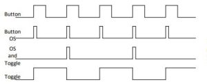
The timing diagram shows the use of one-shots to selectively block the seal circuit Toggle from turning on every other leading edge. The event of the leading edge is isolated using the one-shot and then the blocking contact is inserted just before the seal circuit to set logic on to block the circuit from turning on when the output was already on.
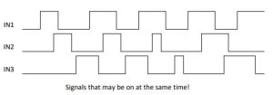
One Shots Used to Remember Order of Events
The following circuit may be useful to remember which of three events turned on last: IN1, IN2, or IN3. An advanced form of this circuit will demonstrate the use of one-shots in logic.
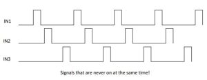
However, if the events overlap or the signals IN1, IN2 or IN3 are ever on simultaneously, then one-shots are needed to separate the events. Notice that if IN1 and IN2 are on at the same time, indeterminate results will occur.
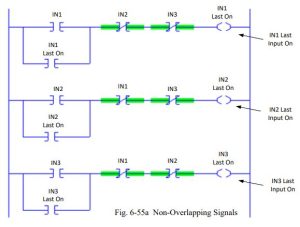
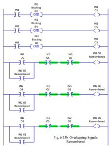
To accommodate the problem of overlapping signals, consider the following improvement to the circuit above. This circuit remembers which leading edge turned on last.
The following program remembers the input that last turned on by remembering a one-shot of the leading-edge of the signal, not the signal itself.
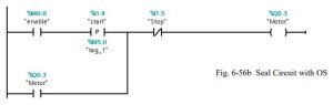
Edge evaluation or one-shot circuits may be included in transferring of a seal circuit to an S/R circuit. Care must be taken when this is attempted as the DeMorgan rules are not necessarily still the only tool needed. For example, if the following seal circuit were evaluated, what would be the equivalent S/R circuit?
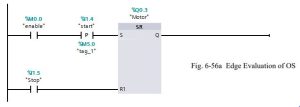
This circuit would be evaluated as follows:
This leads to the observation that as long as the one-shot is involved in the “start” portion, all is well. However, if the “Stop” portion is involved in a one-shot and the DeMorgan Theorem is necessary, a one-shot should be evaluated in coordination with a timing diagram. The inverse must be the inverse in all circumstances with all combinations of inputs evaluated. The one-shot does introduce a problem in using DeMorgan’s Theorem to invert logic and convert from seal memory to S/R memory.
Second Look at the Juice Condenser
Since last chapter, several problems have been introduced, and the juice condenser problem was partially solved but a total solution was delayed until the memory circuit was discussed. The juice condenser problem includes memory that may require a second look. The operation included a fill, a condensate portion and a drain. These operations were not to be overlaid but rather were to be consecutive in nature. This leads to a memory circuit that includes more than one set of events.

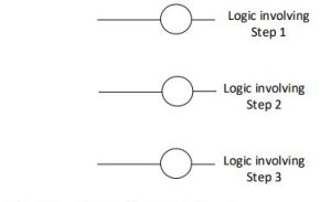
Each memory circuit must be exclusive of the other two events and must occur in a proper sequence. For example, the fill operation must occur first, then the condensate operation and finally the drain operation. This may be expressed using three seal circuits:
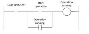
The three operations may be represented by three seal circuits as follows with modifications to follow:
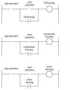
The three operations must be done in order. This requires that before the first operation starts, the requirement that there is not a fill, condensate or drain action presently active must be determined. This can be expressed in the start portion of the fill operation as:
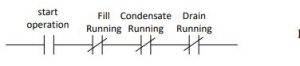
Succeeding operations must likewise be programmed using a start portion with the prior operation present.

The conclusion of this problem is left as an exercise.
Several of the other problems at the end of the chapter use similar memory of logic. The logic may be described also as ‘state logic’ and this will be discussed further in chapter 11. For now, we will use multiple bits to describe states and use the state information to drive the remainder of the programming.
Problem statements for the following three processes also require similar treatment:
Memory Circuit Not Necessarily the Output
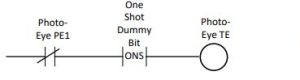
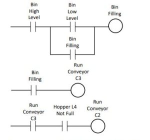
This problem’s problem statement hints that the conveyor C1 should start with the Start Button PB1. But an additional condition involves conveyor C2. C1 needs to turn on and off based on the condition of conveyor C2. This suggests a seal circuit that does not include C1 directly but indirectly. The seal or memory circuit should be an internal bit coil that turns on with the PB1 and turns off when the box has cleared PE1. The conveyor C1 Run should be linked to the Conveyor 1 internal Run bit and the C2 Run bit as shown in the figure below:
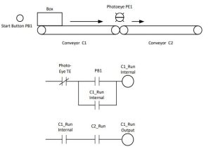
A method for development of the stop bit Photo-Eye TE would be to use a one-shot on the trailing edge of the Photo-eye signal as follows:
Memory Circuits for Competing Resources
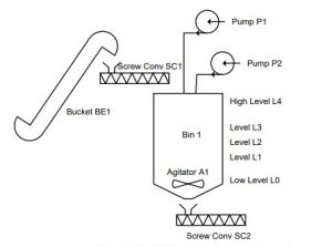
The following conveyor system at first appears very complex but may be divided into a number of smaller areas and programmed by area. For instance, if a bin goes low, it calls for material. The call can only occur if there is not a fill operation already in progress with the other bin. The memory circuits then are developed as follows:
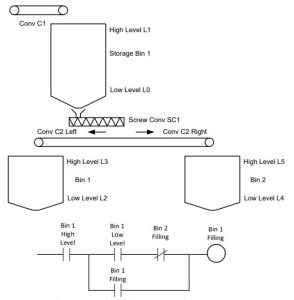
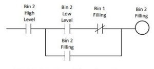
We then work back toward the top of the process. The two memory circuits above determine the state of Conveyor 2. If Bin 1 is filling, then Conveyor 2 Left is on. If Bin 2 is filling, then Conveyor 2 Right is on. If Conveyor 2 is running, then the Screw Conveyor SC1 is on.
Stepping Program
The fill operation for the Storage Bin 1 is handled in a separate memory circuit with its own memory circuit using low and high level to set and turn off the memory circuit. The method of working from the bottom to the top is used in many process programs to control flows.
The following process hints at a stepping program that moves through a number of steps to make a batch. Here the level switches above L0 are intended to determine the fill level for the ingredient. If the solid ingredient delivered from Bucket BE1 is to be delivered first, it is implied that this ingredient fill from Level L0 to Level L1. Since this is not usually the case since a liquid is usually added first, we can assume that either the liquid from Pump P1 or Pump P2 is delivered first to the batch. Then possibly the screw conveyor and finally the second liquid are to be delivered. The batch content and mix procedure are not the topic of interest here, but rather the direction the mix is to take to be made. Many systems such as this are more flexible with a scale weighing the ingredients. Here, the placement of the level switches is extremely critical and fixes the ingredient amounts at the level of the switch. If the weather is more or less humid or the ingredient is not at the precise right density, this method is not good if accuracy is needed.
Downstream Developed First
The problem below has the following general requirement that logic from one section is fed upstream. For problems such as this, the down-stream portion must be activated first. For instance, the last conveyor must run before the conveyor feeding it is allowed to run. Otherwise, you may be the person with a shovel cleaning up a pile of coal at the in-feed to a conveyor.
Always make sure the down-stream item is running and the down-stream hopper is not plugged in order to run a conveyor. Then move back to the conveyor feeding it and continue upstream to the first conveyor. (The first is last and the last is first.)
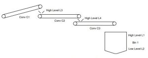
Working back toward Conveyor 1 yields similar results to the logic shown above.
Stepping Program for Machine
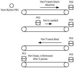
The following machine is designed to move a part down a conveyor and back to home. In the forward movement, the part is to be sprayed after being sensed by the photo-eye in the middle of the conveyor. Once the part moves to the end of the conveyor, the conveyor reverses and the part is moved back to the home position to be removed. A start button begins the action.
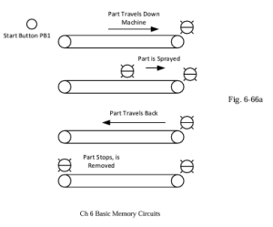
This program requires the operator start the movement by pushing a button. This action sets the machine in motion. Logic can be developed using seal circuits for forward motion, reverse motion and over-all motion. The spray action begins by the part passing the middle photo-eye.
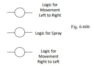
Logic for this machine will be further discussed in later chapters. For now, it is left to the student to create logic to turn on these three coils either using seal circuits or S-R blocks.
Summary
This chapter is useful in the development of logic using memory circuits. The prior chapter was interested in the development of combinational logic. This chapter began the discussion of sequential logic. More on sequential logic will follow.
The fill sequence or empty sequence from a bin or tank requires a memory circuit. This was shown in a number of examples.
Writing of Siemens and Allen-Bradley contact and coil instructions was reviewed. A number of instructions were added in the discussion including memory instructions as well as one-shot or edge trigger instructions.
Emphasis was placed on converting from one style of memory circuit to another. For Siemens and most European designers, the S-R logic dominates. In the US, seal circuits are dominant. To convert from one to the other is a requirement of this chapter. Also, to convert from off- dominant to on-dominant logic is necessary. Also, reasons for using the off-dominant versus the on-dominant logic were discussed.
The various edge trigger instructions from Siemens as well as Allen-Bradley were discussed and examples provided. The purpose of these instructions was addressed as well.
Several example problems were introduced using the memory circuit concept. When more than one state is required, then several memory bits must be used to implement the overall logic.