7 Timers, Counters and T/C Applications
Introduction
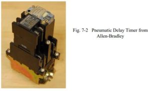
Timers and counters are discussed in the same chapter since most rules apply to both. Timers and counters have been in existence for as long as relays and provide an important component in the development of logic. Timers were constructed in the past as an add-on device to relays slowing down the transition of the plunger from immediately opening or closing. The time delay was accomplished with a pneumatic bladder that allowed the air to escape either quickly or slowly depending on the setting of the timer. Quick was usually less than a second and slow was usually between 30 and 60 seconds. Setting this kind of timer was an inexact science and today’s traffic lights are an example of the fickle nature of timers that seldom respond in exactly the same from day to day and year to year.
For the first time, function blocks are introduced in the rung output position or coil position to provide timer and counter functions. Function blocks allow inputs from the left and pass power through to the right when the function is done or when various conditions are met. Either the timer has timed out or the counter has counted to the preset. Function block usage differs from manufacturer to manufacturer. Function blocks rely on a standard format to enter information about the counter or timer. All variables in the function block must be entered correctly before the device will operate.
Some timers are referred to as retentive. Retentive refers to the device’s ability to remember its exact status such that when the circuit is again activated, the timer continues from the previous point. Non-retentive timers reset to zero and start from zero each time the timer function block is energized. Retentive is similar to blowing up a balloon. One does not blow a balloon up with one blast of air. It takes quite a few. The retentive balloon has a finger along the neck of the balloon holding the air already blown in captive. When more air is blown in, the new air is added to the air already present. Many processes in the factory rely on logic needing this kind of physical property to control a machine.
Other terms used in the timer and counter blocks are “preset” and “accumulated”. These words refer to the preset or target amount and the “accumulated” amount that the timer or counter has built to get to a preset. Times are really counts stored as integer numbers. Thus, counters and timers are very similar. Timers increment a number regularly each time period (usually in increments of 1 msec.).
Timers
Timers are used to provide logic when a circuit turns on or off. Traditional pneumatic timers were provided as either on-delay timers or off-delay timers. Contacts were provided both normally open and normally closed for each type of timer. The timer head was chosen as either the on-delay type or off-delay type. PLCs allow for a quick change from one type to the other with a few keystrokes on the programming panel.
Symbols for Timers:
The following symbols are used for pneumatic timer contacts:
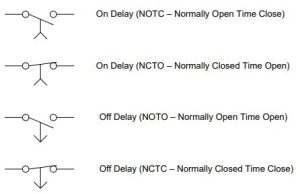
Coils for pneumatic timers are drawn similar to relay coils except that TD is usually included in the label. TD refers to time delay.
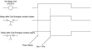
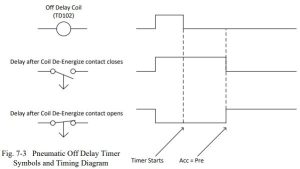
While these timers are only a sampling of the types of different timers, their function describes the main function of all timers, a time delay. While PLC vendors do not need to use the terms of on-delay or off-delay, normally closed, normally open, held closed, or held open, these terms are an important part of design of PLC circuits. Some vendors still use the terms to show linkage between the PLC and the original timer circuits.
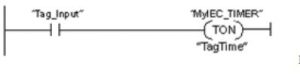
Allen-Bradley provides three timers; TON, TOF, and RTO. All are block-type instructions and are located at the extreme right of each rung used. They are parallel to coils but may not be used in series with each other or in parallel with coils. Each has two coils extending from its right.
These coils are not programmed separately. These coils appear when the timer function block is programmed.
Siemens Timers
First, we look at the Siemens Timer block and discuss the various types of timers available.
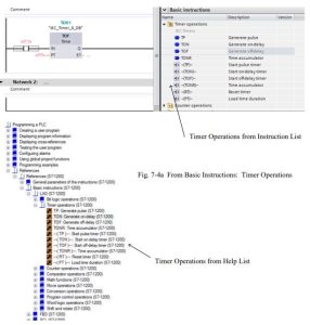
The instructions will be listed below with a brief description from the ‘help’ menu from the TIA portal. A more thorough description may be found in the reference manual for Siemens or in the help menu itself.
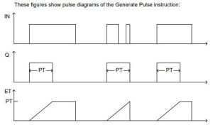
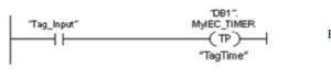
TP: Generate pulse
“The instruction Generate pulse sets output Q for duration PT. The instruction is started when the result of logic operation (RLO) at input IN changes from 0 to 1 (positive signal edge). The programmed time PT begins when the instruction starts. Output Q is set for the duration PT, regardless of the subsequent course of the input signal. Even if a new positive signal edge is detected, the signal state at the output Q is not affected as long as the PT time is running.
The current time value can be queried at the ET output (Elapsed Time). The time value starts at T#0s and ends when the value of duration PT (Preset Time) is reached. If duration PT is reached and the signal state at input IN is 0, the ET output is reset.”
These figures show pulse diagrams of the Generate Pulse instruction:
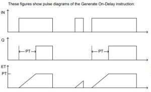
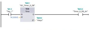
TON: Generate on-delay
“The instruction Generate on-delay delays setting of the output Q by the programmed duration PT. The instruction is started when the result of logic operation (RLO) at input IN changes from 0 to 1 (positive signal edge). The programmed time PT begins when the instruction starts. When the duration PT expires, the output Q has the signal state 1. Output Q remains set as long as the start input is still 1. When the signal state at the start input changes from 1 to 0, output Q is reset. The timer function is started again when a new positive signal edge is detected at the start input.”
These figures show pulse diagrams of the Generate On-Delay instruction:
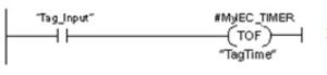
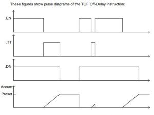
TOF: Generate off-delay
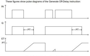
“The instruction Generate off-delay delays resetting of the output Q by the programmed duration PT. The Q output is set when the result of logic operation (RLO) at input IN changes from 0 to 1 (positive signal edge). When the signal state at input IN returns back to 0, programmed time (PT) starts. Output Q remains set as long as the duration PT is running. When duration PT expires, the Q output is reset. If the signal state at the IN input changes to 1 before the duration PT expires, the time is reset. The signal state at the output Q will continue to be 1.”
These figures show pulse diagrams of the Generate Off-Delay instruction:
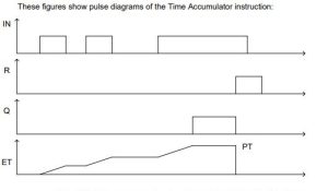
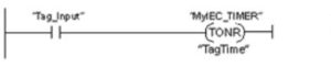
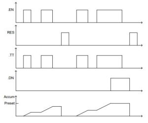
ONR: Time accumulator
“The Time accumulator instruction accumulates time values within a period set by parameter PT. When the signal state at input IN changes from 0 to 1 (positive signal edge), the instruction executes and the duration PT starts. While the duration PT is running, the timer values are accumulated that are recorded when the IN input has signal state 1. The accumulated time is written to output ET and can be queried there. When the duration PT expires, the output Q has the signal state 1. The Q parameter remains set to 1, even when the signal state at the IN parameter changes from 1 to 0 (negative signal edge).”
These figures show pulse diagrams of the Time Accumulator instruction:
These examples give the IEC 61131-3 equivalent of the ‘box’ instructions listed previously:
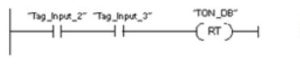
–( RT )—: Reset timer
“The Reset timer instruction resets an IEC timer to 0. The instruction is only executed if the result of logic operation (RLO) at the input of the coil is 1. If current is flowing to the coil (RLO is 1), the structure components of the timer in the specified data block are reset to 0. If the RLO at the input of the instruction is 0, the timer remains unchanged.”
The following example shows how the instruction works:
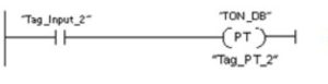
—( PT )—: Load time duration
“The instruction Load time duration sets the duration of an IEC timer. The instruction is executed in every cycle when the result of logic operation (RLO) at the input of the instruction has the signal state 1. The instruction writes the specified time to the structure of the specified IEC timer.”
The following example shows how the instruction works:
Siemens Counters:
Next, we look at the Siemens Counter block and discuss the various types of counters available.

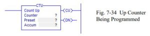
CTU: Count up
“The instruction Count up counts up the value at output CV. When the signal state at the CU input changes from 0 to 1 (positive signal edge), the instruction executes and the current count value at the CV output is incremented by one. When the instruction executes for the first time, the current count value at the CV output is set to zero. The count value is incremented each time a positive signal edge is detected, until it reaches the high limit for the data type specified at the CV output. When the high limit is reached, the signal state at the CU input no longer has an effect on the instruction.”
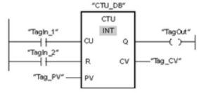
The following example shows how the instruction works:
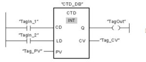
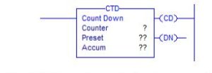
CTD: Count down
“You can use the Count_down instruction to decrement the value at output CV. When the signal state at the CD input changes from 0 to 1 (positive signal edge), the instruction executes and the current count value at the CV output is decremented by one. When the instruction executes the first time, the count value of the CV parameter is set to the value of the PV parameter. Each time a positive signal edge is detected, the count value is decremented until it reaches the low limit value of the specified data type. When the low limit is reached, the signal state at the CD input no longer has an effect on the instruction.”
The following example shows how the instruction works:
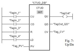
CTUD: Count up and down
“You can use the Count up and down instruction to increment and decrement the count value at the CV output. If the signal state at the CU input changes from 0 to 1 (positive signal edge), the current count value is incremented by one and stored at the CV output. If the signal state at the CD input changes from 0 to 1 (positive signal edge), the count value at the CV output is decremented by one. If there is a positive signal edge at the CU and CD inputs in one program cycle, the current count value at the CV output remains unchanged.”
The following example shows how the instruction works:
Allen-Bradley SLC Timers and Counters
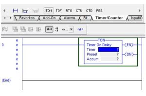
SLC Timer Layout:
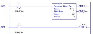
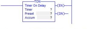
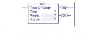
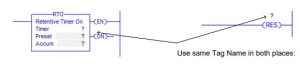
Timer On Delay TON is the non-retentive instruction for on-delay timers. It is used to provide signals that change state a time delay after the TON block is energized. TOF is the non-retentive instruction for off-delay timers. RTO is the retentive timer instruction. It does not reset to an initial value but rather stays at an accumulated value each time the input to the function block is energized. It ‘retains’ the count previously accumulated and continues on from that value. It must be reset with a RES (Reset) command. Reset commands are useful for not only the retentive timer instruction but also any timer or counter with a retentive nature.
Timers are addressed using the T4 file. Three words are used for each timer. These words are set up in a fixed block format as follows:

To program a timer and view its control contacts helps understand the functionality of the timer.
The example below shows the TON timer block with all types of contacts used referenced to output coils. Build this circuit to show delay contacts in action. Another approach would be to view the T4 data file from the project tree with the processor in On-Line Run Mode.
A major difference between A-B timers and counters and the Siemens’ equivalent is that the control bits are built into the A-B devices. The control bits must be added per the Siemens’ explanations. What is tied to the Q output becomes the control bit for a Siemens function.
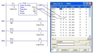
Preset (PRE) and Accumulated (ACC) values can be modified on-line as well as offline. These values are adjusted many times after the program is running in order to eliminate any wasted time in the cycle of a machine. To move a preset from .50 to .05 second can save hundreds or even thousands of dollars in added productivity of a machine over a year’s time. As a rule, these timers are set to the lowest possible value to not damage the machine or cause a problem.
Addresses may use either the specific bit/word or the mnemonic label:
T4:0/15 equal to T4:0/EN (enable contact)
T4:0/14 equal to T4:0/TT (timer timing contact)
T4:0/13 equal to T4:0/DN (done contact)
T4:0.1 equal to T4:0.PRE (preset word)
T4:0.2 equal to T4:0.ACC (accumulated word)
T4:0.1/0 equal to T4:0.PRE/0 (preset word, bit 0)
T4:0.2/2 equal to T4:0.ACC/2 (accumulated word, bit 2)
Entering the instruction requires a time base option. Time bases are .01, 0.1 or 1.0 second. Presets are entered as multiple counts of the time base.
A flashing circuit with two timers:
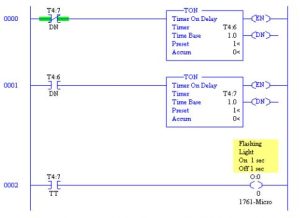
A Retentive Timer does not reset each time the Enable turns off. The ACC (accumulated value) remains unchanged. To turn off a Retentive Timer, a RES (Reset) coil must be energized.
Along with timers, counters are introduced to provide counting functions similar to mechanical counters. Function blocks allow inputs from the left and pass power through to the right when the counting function is done. When done, the counter has counted to the preset.Counters can be either up or down counters. Up counters count from zero to a preset while down counters count down from preset to zero. When the target or preset is reached, the counter-done turns on. Some counters allow counts above the preset and below zero. It is always wise to try any counter using a push-button input before relying on it to control programs.
They require two numbers stored: a preset and an accumulated number. They need two inputs: an enable and reset. And, they have an output that turns on when the accumulated equals the preset.
Counters differ from timers in that the accumulated count moves by one for each new leading edge of the input. The count continues to move until the preset is reached. When the Preset equals Accumulated, the output turns on. If more new leading edges are received, the count continues to climb. The output stays on until the counter is reset. There is no need to have retentive or non-retentive counters since all counters are reset with the RES command. It does not matter how long a signal is on for a counter. The count will only increment one for each new leading edge. Counts are retained after a power outage.
Counters may also be chained together to form very large counts. Counters can count to 32,767. The number 32,767 therefore is the largest preset. If counts climb into the thousands and millions, chaining of counters becomes a necessity.
Can a counter count both up and down? This is a necessity of some counters and all PLC vendors must provide a means to do it. This function will be described later. Several examples of counters will provide practical experiences of how counters are used.
As with all circuits in this book, it is encouraged that students construct the circuit and observe it in action. If each building block is constructed correctly, the whole program has a much greater chance of performing to expectation.
Allen-Bradley provides two counters: CTU and CTD. Both are block-type instructions and are located at the right of the rung similar to timers. Counters trigger or count on a false-to-true transition of the rung logic. Care must be taken to allow sufficient time for the signal to be read by the input card or input point on the fixed I/O processor. If the time of the pulse is less than the time of a scan, the signal will probably be missed. To accommodate higher pulse rates, PLC manufacturers provide high speed counter modules capable of counting pulses to much higher frequencies than by using the CTU and CTD function block.
Counters are addressed using the C5 file. Three words are used for each counter. These words are described as follows:
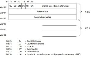
The Count Up Overflow bit is set when the accumulated value increments above 32767 to – 32768 and stays set until the RES instruction resets the count or the count is decremented by 1 back to 32767. The Done bit turns on when the accumulated value becomes equal to or greater than the preset. Enable (either CU or CD) turn on when the rung condition is true.
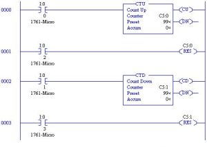
The two counters below are independent. C5:0 is an Up Counter with an ACC starting at 0 and incrementing by 1 with each occurrence of I:0/0. When ACC = 99, the DN bit turns on.
C5:1 is a Down Counter with an ACC starting at 50 and decrementing by 1 with each occurrence of I:0/1. When ACC = 0, the DN bit turns on. Each counter has a reset rung with discrete input control.
To provide a counter that counts both up and down requires addressing the same C5: counter address in both the CTU and CTD block. The accumulated value keeps the characteristic of the CTU counter counting up from 0 to the preset value. This counter can count both positive and negative if accessed by both the CTU and CTD block.
ControlLogix Timers and Counters
Timers and counters are designed in the ControlLogix platform to perform in the same manner as with the SLC family. They must also be capable of functioning in alternate languages such as Function Block Diagram. One nice feature of the ControlLogix timer is the lack of a programmed time base. All timers have a .001 sec or 1 msec time base. Timer preset and accumulated values are stored in DINT (Double Integer) values.
Timer On Delay (TON)

Timer Off Delay (TOF)
The TOF instruction is a non-retentive timer that accumulates time when the instruction is enabled (rung-condition-in is false). The TOF instruction accumulates time until the TOF instruction is disabled or the .ACC ≥ .PRE. This instruction is available in function block and structured text as TOFR.
Retentive Timer On Delay (RTO) and Reset (RES)
The RTO instruction accumulates time until it is disabled. When the RTO instruction is disabled, it retains its .ACC value. You must clear the .ACC value, typically with a RES instruction referencing the same Timer.
Timers and Seal Circuit Combined
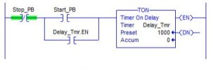
The rung above may not resemble a seal circuit but look at it closely. When Start PB is energized, TON Delay_Tmr.EN turns on providing a parallel path around Start PB similar to other seal circuits. Stop PB energized turns off the circuit. While the circuit should show a NO with the Stop PB input, the use of the NC reminds us that the button was wired to NC contacts.
The seal circuit above is used quite often in sequential logic in which the machine moves from state to state with each new state established with the start contact of the seal circuit. The timer is useful to provide a time buffer between steps. Timers are necessary in this type of program since the machine should be set to move smoothly from action to action. If no time delay is provided between steps, the machine appears to travel in a jerky manner. Many machines will not function well for long without the timer to allow a slight delay between steps. These machines will appear to beat themselves to death.
Timers may be used in chained operations. Timer 1 turns on timer 2 which in turn activates timer 3, etc. Timers are useful in a number of applications using chained timer functions.
ControlLogix Counters
Counters are created in a fashion similar to the SLC counter. Counter types echo the SLC counters. As with timers, counter tags must be created before being programmed.
Count Up (CTU)
When enabled and the .CU bit is cleared, the CTU instruction increments the counter by one. When enabled and the .CU bit is set, or when disabled, the CTU instruction retains its .ACC value. The instruction counts up with each new leading edge at the left of the block. Counts are stored in the .ACC value and range from 2-31 to 231 (-2,147,483,647 to 2,147,483,647). The table of bit assignments for the CTU and CTD counter follow:
.CU BOOL The count up enable bit indicates the CTU instruction is enabled.
.DN BOOL The done bit indicates that .ACC .PRE.
.OV BOOL The overflow bit indicates the counter exceeded the upper limit of 2,147,483,647. The counter then rolls over to -2,147,483,648 and begins counting up again.
.UN BOOL The underflow bit indicates that the counter exceeded the lower limit of -2,147,483,647. The counter then rolls over to 2,147,483,647 and begins counting down again.
.PRE DINT The preset value specifies the value which the accumulated value must reach before the instruction sets the .DN bit.
.ACC DINT The accumulated value specifies the number of transitions the
instruction has counted.
Count Down (CTD)
The CTD instruction is typically used with a CTU instruction that references the same counter tag. When enabled and the .CD bit is cleared, the CTD instruction decrements the counter by one.
When enabled and the .CU bit is set, or when disabled, the CTD instruction retains its .ACC value.
Both the CTU and CTD instruction use the RES instruction to reset the counter’s .ACC value to zero. This is the same RES instruction used to reset the Retentive Timer instruction RTO.
Timer and Counter Examples
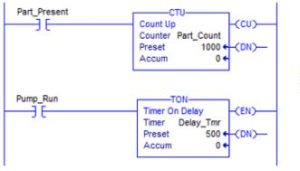
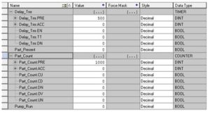
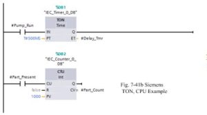
When Pump_Run is toggled on, Delay_Tmr begins to time and Delay_Tmr.DN turns on 500 msec after Pump_Run (Delay_Tmr.EN) turns on. With the counter, when Part_Present is toggled on, Part_Count increments by one. When Part_Present is toggled 1000 times, Part_Count.DN turns on.
These two examples are separate and not linked. The tables for each look very similar, however.
The same examples are next shown with Siemens’ programming:
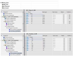
Siemens builds a data block (DB1, DB2) that stores the values of the timer and the counter. The same values are found in the tags created in A-B’s program tag database.
Use the Monitor function to change timer values when several timers need to be adjusted online. The use of the tag database to set timers requires planning to store timers in a common database area. Siemens uses a watch table to change these values.
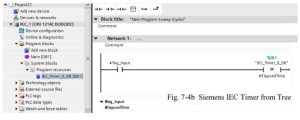
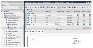
The following screen shows an IEC timer set up for the Siemens PLC. The block constructed is a Function Block (FB1) and the variables are Static. The data type selected is “IEC_Timer” and the name of the timer is “Static_1”. This version of the Siemens timer (and counter) gives the same type of addressing as the Allen-Bradley with a tag (Static_1) providing all variables for the timer.
From the Help Files of TIA Portal:
“Advantages of IEC timers and counters
The universal use of IEC timers and counters makes your program code more efficient. This gives you the following advantages:
• The blocks can be called multiple times with newly generated instance data blocks.
• The IEC counters have a large counting range.
• Compared to S5 timers, IEC timers have better performance and greater time accuracy.
Procedure in STEP 7 TIA Portal
You declare IEC timers and counters in the program block where they are called or needed. The IEC timer is a structure of data type IEC_TIMER, IEC_LTIMER, or TON_TIME and TON_LTIME, for example, which you can also declare as a local tag in a block. The IEC counter is a structure of data type IEC_SCOUNTER, IEC_USCOUNTER, etc.”
The IEC timer and counter are not encouraged except for the fact that they are the only timers and counters available in the FB/DB programming area. This programming area is preferred by many seasoned programmers for the majority of their control code. Thus, the IEC timers and counters should not be ignored.
Seal Circuits with Time Delays
Seal circuits used to start and stop pumps, fans and other equipment many times must interlock with switches to insure safe operation. For pumps, flow switches are used. For fans, pressure switches or flow switches are selected. For conveyor belts, zero-speed or plugging switches are used. If the switch fails or stops, the moving device is also to stop.
The problem is the starting operation. How does the device allow the circuit to start? A timer is used for each of the devices in the process. For instance, if a pump is allowed to start, a timer is also started which times out and then causes the flow switch to activate and stop the pump if low flow is detected. The following circuit shows the operation of this kind of seal logic.
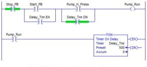
In rung 1 above, the pump starts with I:0/0 (Start_PB). Either the push button I:0/1(Stop_PB) or the combination of I:0/2 (Pump_H_Press) or T4:3/DN shut the pump off. If I:0/1 turns off, the pump shuts down. If I:0/2 shuts off (low pressure), the pump will shut down but only after the time delay of T4:3. The time delay allows time for the pump to build pressure enough to run under normal conditions. If the pressure then fails (turns off), the pump will turn off. Usually this circuit also includes a diagnostic rung which will turn on when the pressure switch fails and the pump is on to alert the operator of the failure of the pump.
From Chapter 6, we remember the following problem:
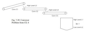
We built Function/State and Signal Assignment Tables for it as follows:
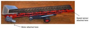
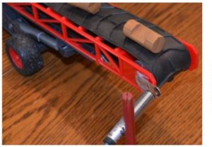
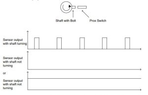
A zero speed switch is usually added to the conveyor to determine if it is running properly. A sensor is attached to the end of the conveyor opposite the motor shaft. This sensor must sense a motion or it will report that the conveyor is not running properly. The input is attached to the shaft. It may be as simple as a bolt that is being read by a prox switch as it passes the switch when the shaft is turning.
As can be seen, both the signal on too long or off too long is reason to report that the shaft is not turning. Both states must be checked. A reasonable time for the shaft to turn one revolution is calculated and a little extra time is added for start-up or stop conditions. Then the timer is added to the motor control program.
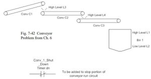
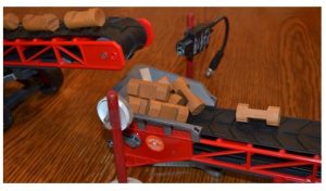
What happens if a conveyor downstream stops working? One sensor is the zero speed sensor from the downstream conveyor. Another sensor is found at the hopper at the beginning of the downstream conveyor. This sensor will turn off the upstream conveyor.
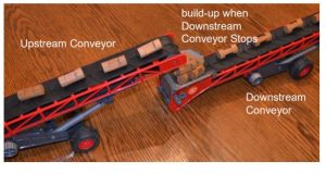
The retro-reflective photo-eye is used here to sense a pile-up at the hopper in the conveyor.
Another timer is used to turn off the conveyor if the conveyor is to be turned off after all product has cycled off the conveyor. The retentive timer is used for this function.
Clocks and Timers
Timers can be used to design clocks. However, they tend to be inaccurate so real-time clocks have been designed into most PLCs to give very accurate times that time stamp events. Clocks programmed with timers lose accuracy when the timer is reset. Usually a scan or two is lost (added) to the time so when the timer is started a 2 to 20 msec delay occurred. Over a day or week, the timer may keep a fairly accurate clock but with time, the clock tends to get farther and farther from the true time. Of course, if the timer is reset once an hour or day with a master reset signal, the timer may mimic a very accurate clock.
More accurate clocks can be built if very long time delays are used. Avoiding the reset scan allows the highest accuracy in clocks.
Since PLC timer simulated clocks are not accurate for most applications, look to the PLC vendor to install a real-time clock. The real time clock is accurate to the same accuracy of the watch on your arm. It is operated with a crystal timer and set by the program and operated by the clock circuit separate from the scan time of the PLC. Most PLCs have built-in real time clocks.
While the A-B SLC-500 processors do not all contain the Real-Time Clock function, they are defined in the larger SLC 5/03, 5/04, and 5/05. Status register addresses S:37 to S:42 define the Real-Time Clock. These registers are defined as follows:
S:37 Clock/Calendar Year Range 0-65535
S:38 Clock/Calendar Month Range 1-12
S:39 Clock/Calendar Day Range 1-31
S:40 Clock/Calendar Hours Range 0-23
S:41 Clock/Calendar Minutes Range 0-59
S:42 Clock/Calendar Seconds Range 0-59
To disable the Clock/Calendar, write 0’s to all clock or calendar words in the range S:37 to S:41.
Combining Counters and Timers
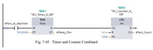
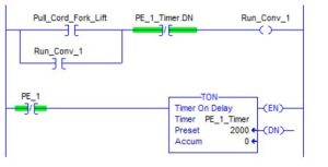
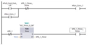
The circuit above uses a timer to provide signal conditioning for the counter IEC_Counter_0_DB. If the input Part_at_Machine does not stay on for at least 500*(.001) sec =
.5 sec, the timer does not time out and the counter does not increment. Circuits similar to the one above are typical for counting of parts. Proximity switchs are especially noisy with multiple transitions on-off-on for each part sensed and need the type of circuit with timer ahead of the counter protects against false counts. Many automotive plants use timer circuits to buffer proximity switch logic to PLC programs
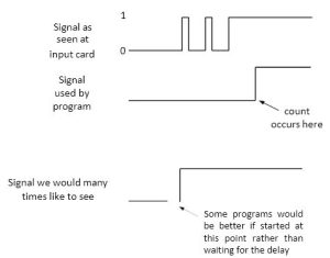
The signal seen at the card many times will be jumpy and not settle for a significant delay period. If the input signal is of this type and many times the prox switch or limit switch exhibits this type of behavior, then a delay such as seen above is needed. The problem with the delay of the TON timer is that the program is delayed from executing even though the switch ‘sees’ the device needed to start the program. The third signal is the one we would more like to see and may be
worth constructing if the program needs to execute immediately with the detection of the switch.
For the counter circuit, the delay is acceptable. For other programs, there should be consideration given for the third signal which would start the user program.
Races using Timers and Counters
A common program to write for timers and counters includes a race condition to determine if a condition is met in a certain amount of time. For instance, the problem to determine if a button has been pushed two times in two seconds is an example of a race. In a race, two events start at the same time. The counter must start counting as the timer starts timing. If the counter reaches the preset prior to the timer reaches preset, the event is determined to be successful. Otherwise, the events are both reset and allowed to start again.
For instance, the programming of the push button to determine if it has been pushed two times in two seconds would resemble:
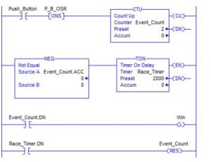
In the circuit above, the counter must reach the preset count of 2 before the timer reaches 2 seconds. The timer starts as soon as the counter is determined to have a non-zero accumulated count. As soon as the counter increments to 2, the latch is set signifying the race was a success. If the timer reaches preset first, the counter is reset and the process begins again.
The option 7.1F uses the race program above but with a change so that if the the count is non- zero (cars present) and the switch does not change quickly (race fails), then move a longer preset to the timer for the turn lane green light:
Add a switch imbedded in the road to sense when there is a back-up of cars wanting to use the turn lane. If there is a back-up, use a longer time preset for the turn lane. If the switch turns on rapidly, then there is no back-up. If the switch turns on but not in rapid succession, there is a back-up.
A Project for Stacking or Grouping Boxes
Example of Counters and Timers in Industrial Application
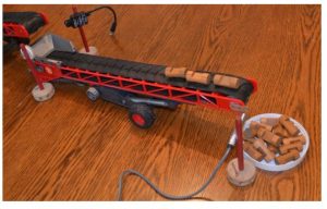
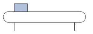
1. Forklift driver places a box on a conveyor:
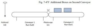
2. The forklift driver pulls a cord energizing an input and starts the box moving to a second conveyor that gathers/groups a set number of boxes:
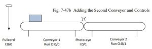
Conveyor 1 runs from when the pull cord is energized until the photo-eye sees the box in front of the eye. It then continues to move until the eye is no longer covered. Conveyor 2 moves from the instant the photo-eye sees the box until a delay after the box no longer is seen.
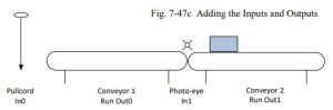
The second conveyor doesn’t stop until a delay after the photo-eye does not see box. Program for Control of Boxes on Two Conveyors:
Use of the Off-Delay for movement of the box past the photo-eye by a set-time positions the box on conveyor 2. The second box placed on conveyor 1 would be positioned on conveyor 2 similar to the first box.
Boxes are grouped on conveyor 2 until a preset count is reached. The preset in the Up Count Counter sets the limit of number of boxes to be collected on the second conveyor.
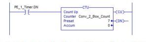
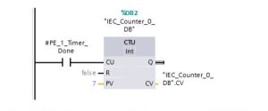
When this counter counts to preset, the number of boxes on Conveyor 2 has counted to 4 and the boxes are now ready to be moved as a group to a third conveyor.
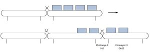
The question about modes will be discussed in a later chapter. To count the boxes off Conveyor 2 requires using a second counter or a down counter with the same address as the up-counter for counting boxes onto conveyor 2.
Timers and counters are used together in a number of different kinds of programs. These show just a few of their many uses in automation programming
Stepping Program for Machine
The following machine is designed to move a part down a conveyor and back to home. It was originally introduced in Ch. 6. In this chapter, we add a timer at the end of travel to give the conveyor some time to stop before reversing.
In the forward movement, the part is to be sprayed after being sensed by the photo-eye in the middle of the conveyor. Once the part moves to the end of the conveyor, the conveyor reverses and the part is moved back to the home position to be removed. A start button begins the action.
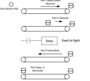
This program requires the operator start the movement by pushing a button. This action sets the machine in motion. Logic can be developed using seal circuits for forward motion, reverse motion and over-all motion. The spray action begins by the part passing the middle photo-eye. The timer is added to let motion come to a stop before the conveyor reverses.
After All This
The original PLC manufacturer, Modicon, came to terms with timers in a much simpler manner than either Allen-Bradley or Siemens. They used a single block that could be programmed either as an On Delay or Off Delay, with either Non-retentive or Retentive capabilities:
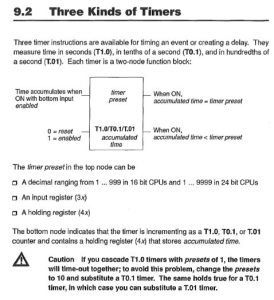
The above is from the Modicon 984 Systems Programming Manual and is the entire description of timers for the Modicon 984 PLC. Similar timers were available for the Modicon 484 and 884. How did they do it, provide all the timing functions necessary with just really one block? The block is very versatile and can be used in a number of different modes and can be cascaded left- to-right. This points out that the complete list of different timing functions is not really all that necessary.
Most of my programming life was spent only knowing how to program the TON timer for a specific PLC. With this one timer, one can get most of the functionality of the other timers with only a few modifications. Is it worth looking into all the various timer types? Usually only if the timers are used by someone else in a specific program, do we need to refer to the manual for those timers other than the TON timer.
Summary
The chapter on Timers and Counters introduces these devices and gives practical examples of their use as well as timing diagrams for applications utilizing their specific qualifications.
Examples show a need to be able to use timers in seal or memory circuits. Use of timers and counters together is discussed.
Siemens and Allen-Bradley based timers and counters are shown and examples of each type are explained. While one might be interested in the specific attributes of each type, it is possible to walk through the chapter and understand the various timers without learning how to use each of the various types. To use the TON or on-delay timer in almost all occasions is possible with a rare need to use alternates. This approach has been used by the author and has worked in industry. This advice is to work extensively with the TON timer and learn its characteristics and use the timer for as many applications as possible. If another type is absolutely necessary, then read about it and use it as necessary. A search of the problems at the end of the chapter reveals that they may all be solved with the TON timer.
An example of a conveyor system counting boxes is discussed and the use of timers and counters to control the movement on the conveyors is shown.
One difference between the Siemens Up-Down Counter and the A-B Counters is that Siemens uses a different counter instruction for up, down and up-down. A-B uses different instructions for up and down but combines the two instructions to allow an up-down counter. The tag for the up-down counter is the same tag. This may confuse at first but should be tried in the labs to see the results. A troubleshooting note on the A-B up-down counter is that one may program one
up-count and one down-count counter with the same tag but not three or four counters with the same tag. This will lead to unexpected results and a troubleshooting dilemma.
While Siemens uses multiple types of timer with the box structure and the IEC type, it is best to settle with the box type and stack them left to right on the screen. A-B allows some stacking of boxes from left-to-right as well. The student should be willing to try to stack instructions and see if the processor will allow this action.