
1 Introduction to PLCs
Programmable logic controllers (PLCs) were introduced to industry between 1968 and 1970 as a way to replace large expensive panels of relays, timers, and counters. Automotive manufacturers were looking for ways to simplify start-up of new car lines after model changeovers each year and save money in the cost of manufacturing installations.
Historically, relays have been used since the late 1800’s to control simple processes. They were used in the early days to control railroad crossings. Before simple relay logic was introduced to control railroad crossing arms and alarm lights, accidents at these crossings were contributing to a high toll on human life.
The term “relay” was coined as the name of the device invented by Samuel F. B. Morse who invented the telegraph. The relay was invented as a device to extend the signal or “relay” the signal of the telegraph more than the 20 mile limit of electrical signals at the time of the invention of the telegraph (1836).
Relays, timers, and counters had been the favored choice for electrical and systems engineers to manufacturing facilities, especially in facilities with a large number of machines making discrete parts. Automotive manufacturers top the list of this type of manufacturing. At the same time that costs continued to rise for the engineering and construction of automotive assembly lines, computers were becoming more numerous and less costly. There was, however, a general discomfort among engineers to replace relays with computers. Most were reluctant to place the computer on the plant floor. A compromise was necessary for the engineer that he would be willing to accept. A computer that appeared to be relay-ladder logic to the electrician but able to use the computing capabilities of a computer was the device envisioned. The result of this vision is what is known today as the PLC (Programmable Logic Controller).
Relays as well as timers and counters were the first devices replaced by the PLC. Relays are electromechanical devices that use magnetism caused by power flow through the circuit’s coil to energize a core and move a plunger with contacts attached. Contacts change state when the coil is magnetized. Normally open contacts close while normally closed contacts open. Changing contacts combine to complete other circuits. Combinations of relay contacts energizing coils form the basis of Boolean logic. Boolean logic deals with the combination of discrete on-off states to turn on or off other outputs.
A History of Automation in the 60’s and 70’s
The principle of using PLCs as substitutes for relays to reduce the wiring, panel fabrication, and engineering cost looked very appealing to the early PLC user. Like most electronic devices appearing in the early ’70’s, cost of the early PLC was high and functionality was not well developed. Early PLCs were developed around a mini-computer or special purpose control board. It was not unusual to pay $50,000 or more for a single PLC complete with I/O and still use relays for the most critical circuits. These hybrid designs existed for many years until engineers became convinced that PLCs were as reliable as the relay and could be trusted equally to the relay circuit being replaced. Hybrid circuits using both relays and PLCs existed for many years but have become too expensive for most automation applications in today’s market.
In a quote from Programmable Logic Controllers: An Emphasis on Design and Application (Erickson, 2005) about the early PLC:
“The machine tool and automotive industries were large users of relay control systems. A simple machine tool would require six months to a year to completely debug (Morley, 2001). Every year, automotive manufacturing facilities would be shut down for two to three months in order to implement the changes due to the new automotive models. The lost production due to these changes was significant.”
Richard (Dick) Morley was credited with the invention of the modern PLC. Morley worked for Bedford Associates in Massachusetts in 1968 when the PLC was first conceived. Dick Morley later wrote a book, History of the PLC in 2001 published by R. Morley Incorporated. Morley is commonly considered the father of the PLC.
Another quote from Morley in addressing the toughness of the PLC supplied by Bedford Associates, the Modicon controller from Morley’s text and found also in Erickson’s text:
“Landis [a machine tool company] decided to purchase the MODICON units and not use the PDP-14. When DIGITAL [sic] tried it get back into Landis, Landis wrapped a welder cable (operating) around the 084 and poured Coke over the unit. The 084 kept right on trucking. Digital retreated with grace.”
Other anecdotal competitive stories abound and make up part of the folk lore of the early PLC. One about a PLC using 15 volt logic shows the competition between early PLC vendors. The vender owning the 15-volt PLC inserted a spark plug in a waveguide and entered a vendor’s show with the noise gun in hand (carefully concealed in a briefcase). All of the PLCs were successfully shut down when the waveguide was pointed at their machine except the 15 volt model. This actually happened in the early race to be the best and the toughest PLC in industry. Toughness (in this case, noise immunity) was very important to the manufacturing engineer. What happened to the vendor of the 15-volt PLC? Today this vendor no longer is in the PLC market, displaced by the strong competition in the manufacturing marketplace.
There has been a great deal of interest about the origins of the PLC since those who were responsible for the origination of the PLC have retired and many have passed on. The competition for the selection of the first successful PLC is very interesting. It is repeated in the following article by Randall Brodzik, a writer for Control Engineering and found in article: Inside the competition for the first PLC.[1]
Inside the competition for the first PLC
1971 The race to develop the first programmable logic controllers was underway inside General Motors’ Hydra-Matic Transmission Division in Ypsilanti, Michigan, in 1970. Three finalists had very different architectures.
“In 1970, a fierce contest was being waged inside General Motors’ Hydra-Matic Transmission Division in Ypsilanti, Michigan. At stake was program ownership of what would become the first programmable logic controllers (PLCs), and the outcome would shape not only the design of the first PLCs, but also the success or failure of their advocates.
PLC incubator
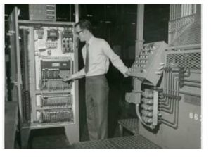
It was natural that GM’s premier manufacturing technology group, Hydra-Matic, would be the incubator of the PLC. A nationally recognized technology leader, Hydra-Matic had installed one of the early IBM 1800 computers, the IBM 1801.
Richard Lundy, an owner of one of the original PLC suppliers, tells the story of when Ed O’Connell, a Computer Group engineer, didn’t think GM was getting enough support from IBM. ‘An entire test line was running off of the one computer,’ Lundy said, ‘which made it very vulnerable, and Ed didn’t like the support he was getting. So he called Watson.’ That’s Thomas Watson, Jr., the son of IBM’s founder and company CEO. Support for Hydra-Matic’s IBM system quickly improved.”
In the following, Dave Emmett is described as the developer of the ‘Standard Machine Controller’.
“In April of 1968, a young Hydra-Matic engineer, Dave Emmett, proposed the development of what he called a ‘Standard Machine Controller.’ The controller he envisioned would replace the relay systems that controlled machine operations. Emmett was in charge of the Circuitry Group, and he envisioned a machine that would reduce maintenance costs, improve machine diagnostics, and decrease panel space.
Randy Brodzik, who later worked for Emmett, remembers that Emmett had a clear vision of what was needed: ‘Dave said the goal was to develop a technology that would significantly reduce the time it took to make changes to a machine control sequence. With relays, first you had to do all the documentation, and then change all the wiring. It would take hours.”
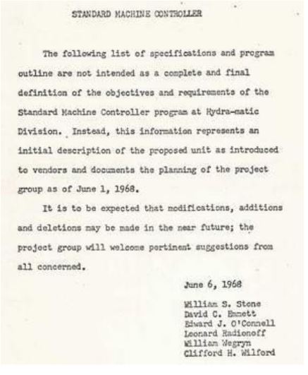
The letter was the original invitation for vendors to supply a system that would become the original PLC for GM.
Another group also was involved at GM. The description of this group follows:
“At about the same time, another group in Hydra-Matic was envisioning a different type of machine control system for GM. The Computer Division had hired Information Instruments, Inc. (3-I) to create a computer controlled assembly machine for the forward clutch line. This new control system had no limits to the number of elements in a ladder diagram, included parallel processing, and could incorporate complex Boolean equations.
Richard Lundy, a program manager for 3-I at the time, said the competition between the two Hydra-Matic Groups was ‘pretty dramatic.’ He described the Circuitry Group as wanting to duplicate existing ladder diagrams, while the Computer Group wanted to use nonsequential programming, similar to that used in current end-of-line test systems, to provide a more robust instruction set and reduce processing time. The advantages and limitations of each approach would become clear as the project progressed.”
Finally, a specification was written and shopped that would deliver a completed system. The RFP was a Request for Proposal. This form is described in the following:
“In April and May of 1968, work was done on a request for proposal that is remarkably simple by today’s standards. The RFP, issued in June 1968, included only four pages of design specifications, including a requirement that ‘memory word length shall be at least eight bits.’ Douglas Brant worked on specifications for equipment coming into Hydra-Matic. He said that there was a strong rivalry between the Computer Group and the Circuitry Group in developing the specifications. ‘I guess it boiled down to people’s territory,’ Brant said.
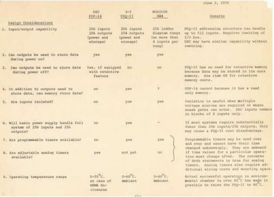
Of the many companies who received the RFP, three were selected for evaluation: Digital Equipment Corporation (DEC), 3-I, and Bedford Associates, a consulting firm. Its products were the DEC PDP-14, the 3-I PDQ-II, and Bedford Associates’ Modicon 084. (The Modicon name came from MOdular DIgital CONtroller.)” See the following evaluation of the three finalists:
A PLC was installed at GM in June 1969. Its description follows:
“In June of 1969, DEC’s PDP-14 was installed to control a gear grinder. Richard Lundy says that in spite of a very strong GM-DEC relationship, DEC’s concerns about memory failure significantly limited the PDP-14’s competitiveness. To make a change to the DEC program, ‘you had to send the client program in to them, and they would send you back a hardwired memory board,’ Lundy said. Having to remove a controller’s memory from the plant to make changes would prove to make the DEC option unsustainable.
Richard Lundy’s company, 3-I, was aligned with the Hydra-Matic Computer Group. Lundy said that during the evaluation period, the rivalry between the Computer Group and the Circuitry Group escalated. To the Computer Group, the advantages of higher level logic capabilities were clear and the selection of the PDQ-II was an obvious one. The 3-I solution for the forward clutch line, with its complex programming, had performed beautifully. Lundy said the PDQ-II quickly became known within the Computer Group as ‘pretty damn quick.’
Emmett and the Circuitry Group advocated strongly for the Modicon 084. The programming that was seen as a benefit by the Computer Group was seen as a detriment by Emmett’s team. Because Modicon’s programming language was similar to the Group’s familiar relay ladder diagrams, it was expected to provide the smoothest transition and lowest cost for training and support. Randy Brodzik recalls that Emmett had an implementation view of the project: ‘He said that in order for this new technology to achieve wide acceptance, it needed to emulate what was already in place.’
As an added bonus for Modicon, the 084 was the only controller built into a hardened package, providing plant floor protection that the other two options did not. And Modicon won.”
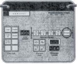
This is the original Programming Panel for the Modicon 084. Yes, the numbers were thumb-wheel switches which were very hard to turn and left fingers with callouses after entering a program. Note that there is no recording mechanism yet. That will come later.
Definitions of the PLC
NEMA’s definition (NEMA or National Electrical Manufacturers’ Association) of a programmable logic controller is “A digital electronic apparatus with a programmable memory for storing instructions to implement specific functions such as logic, sequencing, timing, counting, and arithmetic, to control machines and processes.” This definition gives a good summation of the functionality of the modern PLC. A PLC must have each of these functional components to be considered a modern PLC. Primarily, the PLC is used to control machines. Programmable logic controllers have varied widely in what is considered a process or a machine. A few PLCs have even been used to control the duration of water for irrigation systems or lawn watering control. The view of what is a process has widened through the years. The modern PLC may even used to control the ingredients sprayed on a car moving through an automatic car wash.
A definition of the PLC from Liptak’s Process Control states:
“A programmable logic controller (PLC) is an industrially hardened computer-based unit that performs discrete or continuous control functions in a variety of processing plant and factory environments.”
These definitions of the PLC, either from NEMA or Liptak, give an overall picture of a computer with a special functionality partial to the automation market and able to control a variety of different machines. The purpose of this text is to more fully understand the use and programming of a PLC and understand applications of PLCs in factory automation.
In the US, the general trend was for the PLC to emulate or copy ladder logic as employed in the standard relay ladder logic or schematic drawing of the day. In other parts of the world, as the PLC was studied, this was not necessarily the case.
In Germany, for instance, STL or Statement List was introduced. From the Siemens book: Milestones in Automation by Arnold Zankl is the following quote (p. 54):
“Siemens had at first used STL programming exclusively and had been very successful with it.
It seemed reasonable to program something in the way people think of it and describe it verbally. High education standards in Germany and Europe also supported this approach.
In the US, where training for skilled workers was generally less intensive than in other countries, the ladder diagram, derived from the circuit diagram, dominated from the start.”
While this statement may not be meaningful to some, the choice of American PLC vendors to pursue Ladder logic while the German PLC vendor Siemens pursued another language, STL, was significant and has had an impact on the marketplace. While the German machine later embraced Ladder as a second language, the reverse has not occurred to any degree with the American market keeping strong ties to Ladder and not embracing other languages. Understanding a variety of languages and being able to program in the language most appropriate for the application is of primary importance and should be a student’s goal.
Evolution of the PLC
From that beginning, PLCs have grown in popularity and capability to the extent that they can be found in some part of almost every industry. PLCs are produced by a variety of companies worldwide and several companies that made PLCs in the last 30 years have been forced out of the business by ever increasing competition.
Listed in Table 1-1 below is a time line of the evolution of the PLC from its inception to the modern PLC. See Table 1-1 for a portion of the time line for PLC development. Table 1-2 describes the Siemens PLC and its parallel development in the European market place.
History of Programmable Logic Controllers (PLCs)[2]
| 1968 | Design of PLCs developed for General Motors Corporation to eliminate costly scrapping or assembly-line relays during model changeovers. |
| 1969 | First PLCs manufactured for automotive industry |
| 1971 | First application of PLCs outside the automotive industry |
| 1973 | Introduction of “smart” PLCs for arithmetic operations, printer control, data move, matrix operations, CRT interface, etc. |
| 1975 | Introduction of analog PID (proportional, integral, derivative) control, which made possible the accessing of thermocouples, pressure sensors, etc. |
| 1976 | First use of PLCs in hierarchical configurations as part of an integrated manufacturing system |
| 1977 | Introduction of very small PLCs based on microprocessor technology |
| 1978 | PLCs gain wide acceptance, sales approach $80 million |
| 1979 | Integration of plant operation through a PLC communication system |
| 1980 | Introduction of intelligent input and output modules to provide high-speed, accurate control in positioning applications |
| 1981 | Data highways enable users to interconnect many PLCs up to 15,000 feet from each other. More 16-bit PLCs become available. Color graphic CRTs are available from several suppliers |
| 1982 | Larger PLCs with up to 8192 I/O become available |
| 1983 | “Third party” peripherals, including graphic CRTs, operators’ interfaces, “smart” I/P networks, panel displays, and documentation packages, become available from many sources |
Table 1.1 Early History of the PLC
The PLC is an American invention but the European manufacture Siemens was quick to augment its automation offering to include its own PLC. The first PLC comparable to the American equivalent is the S3, Siemens’ first storage programmable PLC. From Milestones in Automation by Arnold Zankl of Siemens is the following history of the Siemens history of automation control and the PLC in Europe.
| 1957 | First prototype controllers from Siemens with germanium transistors |
| 1964 | Second generation control and switching systems introduced with board-design using Eurocard |
| 1971 | Third generation controllers introduced
S1 – using hard-wired logic S2 – using electronic sequence processor |
| 1973 | S3 – first storage programmable PLC from Siemens (Simatic S30) |
| 1976 | First fault-tolerant and safety-related PLC for burner controls |
| 1979 | Simatic S5 introduced |
| 1984 | S5-135U multiprocessor PLC with up to 4 central processors for high-speed application |
| 1986 | Introduction of distributed I/O for Simatic |
| 1988 | Introduction of S5-155U with multiprocessor technology including floating-point arithmetic |
| 1994 | Introduction of Simatic S7 |
| 2000 | Integrated drive systems |
| 2002 | TIA Totally Integrated Automation links data to IT domain |
Table 1-2 History of the Siemens PLC
The advancement of PLC technology continues to the present day with newer PLCs introduced to meet the customers’ demands. While early milestones of Table 1-1 show a general direction of the PLC toward a modular device capable of communicating to I/O, a programming terminal and to other PLCs, the PLC of today is also capable of communicating over a highway to a Human Machine Interface (HMI). PLCs are also capable of reading I/O from a variety of sources including I/O through other PLCs. I/O may be distributed using a number of different configurations. Some I/O may use a proprietary network while other I/O may use a public network or highway such as Ethernet. Connectivity to intelligent devices has increased through the years as well with PLCs interfacing to most types of manufacturing equipment such as bar code readers, weigh scales, servo motors and other intelligent devices.
At one time PLCs were simply known as the PC. With IBM and the introduction of the personal computer, naming standards had to change. PC was used for the personal computer so PLC manufacturers changed the name to Programmable Logic Controller. At some time during this early development of the PLC, Allen-Bradley trademarked the PLC name. The name PLC has been used by most engineers to describe the product known today as the programmable logic controller.
Liptak reasons for the popularity of PLCs are:[3]
- Ease of programming and reprogramming in the plant
- A programming language that is based on relay wiring symbols familiar to most plant electrical personnel
- High reliability and minimal maintenance
- Small physical size
- Ability to communicate with computer systems in the plant
- Moderate to low initial investment cost
- Rugged construction
- Modular design
The programmable controller of today has grown in capability and shrunk in size from the first and second generation PLCs of the 1970’s and 1980’s. Where relays, timers, and counters were the concern of early design, inclusion of numbers and numeric manipulation quickly became part of the PLC. Instructions for comparing, adding, subtracting, multiplying and dividing of numbers were added to the language. As engineers demanded more sophistication from their PLC, designers turned to the microprocessor and, in part, emulated the instruction sets of the popular microprocessors of the day. Shift, Rotate, AND, OR, XOR and other instructions from the microprocessor were added. Finally added were floating point numbers and more sophisticated instructions to handle complex algorithms such as the FIFO and LIFO stack operation and the PID block.
The German manufacturer Siemens first introduced Statement List as its primary language for the PLC. Statement List or STL was introduced to incorporate the power of the microprocessor. This was accomplished by implementing a version of assembler language, a more difficult language to master but one that was more flexible than Ladder. In general, the German Siemens is considered more powerful but difficult to learn. Implementation, on the other hand, is usually simpler with the Siemens approach. As the text is used, hopefully these opinions will become more evident.
Step 7 is the programming language used to program the Siemens PLC. Newly introduced is Step 7 Basic for the new Siemens 1200. Later, the same language introduced for the 1200 will be introduced in the 300 and 400 lines of processors. STL will give way to SCL, a Pascal-type language and the assembler language will be dropped. While different languages will be used for different applications, Ladder or LAD will suffice for many early applications. Becoming familiar with LAD and its use will be a primary early concern. Later, use of Function Block and SCL will provide methods to better describe some applications. Also, the use of grouping of logic into function blocks will provide a method of encapsulation of logic similar to the programming language C’s function, structure and class environment.
A look at hardware is important but will not be stressed. The use of language for development of control of a process will be stressed. Hardware changes with cost and function. Use of hardware for writing programs is necessary. Study of certain types of hardware instead of the programming will not be emphasized.
S7 refers to the newer lines of processors from Siemens. There is a S7-200 which is being phased out with the 1200’s introduction and the S7-300/400 lines. The S7-200 has little in common with the 300/400 since it was developed by the TI engineers at the time that Siemens purchased the TI PLC division in the early 1990’s. The earlier S5 processor also is being phased out. It is an older model, a contemporary to the Allen-Bradley PLC-2 and PLC-5 processor.
From an article on the Omron website:
“S5 is an old model, who was a contemporary of AB-2-PLC and PLC-5. S5 is the Intel 8031 series of microprocessors, which Siemens has licensed the production is based. They also own a coprocessor, which is used in some models S5 gear single Boolean logic. Siemens pressed overwhelming number of features from simple 8-bit processor. Punishment for this, however, that a statement S5 was very primitive and only slightly higher than the 8031 assembler. Look at the 8031 assembly and S5 Instruction List (IL), and you see the similarities. In contrast, AB has a different approach and use the mini-computer technology in their designs early PLC. Early PLC2S used 4 processors AMD 2900 bit slice to a separate 16-bit processor. It was expensive in terms of hardware, but they had fewer restrictions in the software caused.”
The use of PLCs gives one the reason why a language such as LAD is used instead of C for writing programs for manufacturing applications. It is simply quicker and cheaper to write. It is interesting to note that the PLC is perhaps changing its name again (from PC to PLC first) to PAC (Programmable Automation Controller. This new name may never catch on with some but for the newer embedded control processor of today, it may.
The Allen-Bradley PLC has endured from the beginning. After overtaking Modicon in the early 1980’s, A-B never looked back at competition in the US (except for today’s challenge from Siemens). The need for a fundamental knowledge of Allen-Bradley programming is required as well as Siemens. Today, both are required.
The PLC’s Microprocessor Background
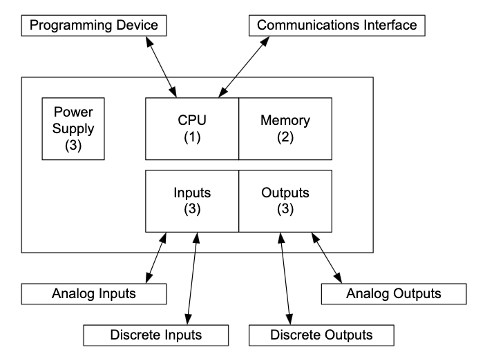
PLCs are closely related to computers because of their computational abilities and logic solving speed. PLCs receive inputs, solve logic, and set the appropriate outputs based on the inputs and programmed logic. Unlike computers, a program in one part of the PLCs memory cannot lock out a program in another part of memory. An errant program statement cannot cause all programs to stop execution, a very important concept if electricians and people other than the original programmer are to be allowed to change program statements. However, with advances of instruction sets to include program interrupt instructions, it is not always guaranteed that one part of a program will not interfere with another and even stop execution of the system.
The PLC can be broken down into these four basic components:
- Central Processing Unit (CPU)
- Memory
- Inputs and Outputs (I/O)
- Power Supply
Storage memory provides for variable storage and retrieval. Recipes and other table information reside here as well as the variables used in logic. Programming more sophisticated applications such as recipes hint at the using the PLC for more sophisticated applications. A basic rule for LAD logic has been that it must be maintainable by people other than professional computer programmers. This includes maintenance personnel who will be used to maintain the system once installed in a plant. As programs grow in complexity and length, ways have been sought to again make the logic simpler to implement and trouble-shoot. Although memory is used for a number of functions, the use of LAD only as a language in the PLC falls short in its ability to handle complex data storage and math arrays. Also, because of the complexity of larger programs, a change in one area can affect other areas, causing hardship when changes need to be made. Language selection is the most important aspect of application development.
Many “religious wars” were waged in the 1990’s involving the choice of the PC or PLC for automation. Those using the argument that the PLC would be out and that PCs would be found in all applications, while not discounted, were not considering the unique capabilities that PLCs had that the PC could not be counted on to deliver. The PLC could be counted on for their ruggedness and ability to restart even in the most difficult conditions. Distributed I/O was counted on to read on a consistent basis all the I/O in the system and report to the cpu. What PCs were capable to deliver was the openness and flexibility and very high performance levels. PLCs have always lagged their PC cousins in these areas but have not given ground based on their overall advantages that cannot be discounted such as ruggedness.[4] describes the choice of PC or PLC: “Experts estimate that in 2005 over 90% of all automation solutions were implemented with programmable controllers. So, contrary to many forecasts, the PC has not replaced the standard PLC.”
The PC will not displace the PLC but which PLC emerges as the dominant platform or language is still to be determined.
PLC Hardware and Safety
Inputs are devices such as limit switches, push buttons, photo-eyes, proximity switches, and relays from other systems. Outputs are devices such as lights, relays, motor starters, solenoids. Motors and other outputs capable of producing motion must be controlled in such a way that the machine is run safely. The PLC must control the process safely from the moment the machine is turned on until the machine is turned off for the day or year. PLC programs must be written in such a way that all events of the machine are monitored in order to guarantee a safe and orderly control of the machine.
PLCs were not viewed as being as safe as relays when first developed. Engineers did not trust the computer as much as the simpler relay. This view changed as PLCs became more reliable. Interestingly, PLCs were made to resemble rugged equipment so engineers would accept them in the rugged industrial environment. Today, PLCs are manufactured that easily could fit in the palm of one’s hand. These PLCs have the same error checking and hardware ruggedness as the big PLC of the 1970’s. Ironically, these little PLCs have much more functionally with far superior instruction sets and faster scan times. They remind one of the evolutions of the hand-held calculator or the personal computer as the old box has given way to the more powerful yet less expensive new box.
The design of the functional aspects of the system must include all the electrical and programming aspects of the system as well as the mechanical, fluid power, air power and guarding systems.
The safety system runs in tandem with the production system. It must not impede the production system but run in parallel with it and oversee any hazards. The focus of the two systems is somewhat different. The production’s system focus is on throughput. The safety system is focused on protection.
A safe system is not entirely possible and a risk is always present. The purpose of the safety system is to reduce the risk to acceptable levels. An absolutely safe system is not possible.
How PLCs Solve Logic
Programming a PLC requires a program that solves the same basic logic again and again guarding against the unexpected and keeping the machine running in an acceptable manner. There must be an orderly flow to the logic to control the machine. PLCs all follow the same general format utilizing the following four steps:
- initialize from a safe state – usually off
- sense inputs
- solve logic in the program
- outputs turned on or off to mechanical devices
Steps 2, 3, and 4 are repeated again and again very rapidly to provide the orderly solving of logic and simulation of relays, timers, and counters. The process, while involving a number of complex actions, breaks down into the following:
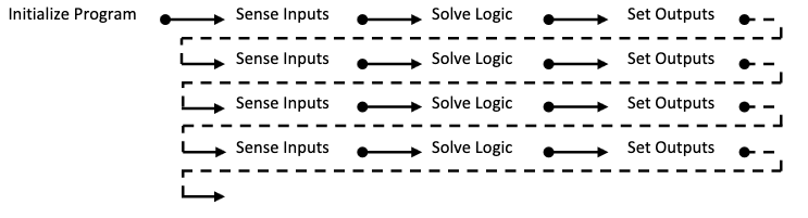
This process repeats each one to 5 millisecond and is referred to as the scan of the PLC. Each repeated sensing of inputs, solving of logic and setting of outputs is a scan of the PLC.
Siemens describes the cycle time of a processor as the entire time needed to read the inputs, execute the program one time and process the outputs. Their blocks are divided into networks and each network is divided into a number of statements. The time line is described as follows:

There must also be an easy way to start and stop the PLC and its program from executing. This is referred to as the modes of stop and run (or program and run). A running PLC program is analogous to turning on the power to a relay panel. When power is turned on, the machine responds in an orderly way per the design of the engineer and the wiring of the electrician. Likewise, when the PLC is turned from program to run, the CPU begins executing the application based on the rules of the program. These rules form the basis for the operation of the system. First, outputs are defaulted to an off or pre-defined state. Then, as the inputs are read, the program is solved sequentially one logic statement at a time. Outputs are turned on or off based on the program and the input conditions. If a program is written and configured correctly, the outputs should fail to a safe state. Some outputs may be required to turn on if the processor fails. Most devices are designed so that if the controller fails, the output turns off and the device being controlled returns to a safe state. In other words, most but not all outputs turn off when the program returns to the program or non-running state. For safety’s sake, design a system to return all outputs to the safe state, either on or off, when the program is not actively running a machine. And when the program is running a machine, devices are programmed to run in only a safe manner. This is a main concern of the programmer, to design a safe machine as well as a working machine.
Richard Morley describes in his own way the invention of the PLC through a number of youtube videos. While they are not the most watched videos on youtube, you may try them sometime. It is interesting to note that the philosophy of creating the PLC was for simplicity and the use of ifthen statements. Really, all the statements are of this type – if-then.
PLCs in World Economy
Manufacturers of PLCs have been many and varied in the past with a stiffening competition over the last twenty years. The effect has been a thinning of the ranks of PLC vendors. It costs much more to bring products to market than it did a few years ago. Foreign competition has caught up and in many ways surpassed domestic PLC manufacturers’ technology. A number of buy-outs, consolidations and joint operating agreements have thinned the number of PLC manufacturers to a few. Allen-Bradley is the mainstay American company producing PLCs. Also in the US are General Electric and the combined Modicon-Sq D PLC organization. Siemens in recent years has made significant inroads in the US market and overtaken all but Allen-Bradley. In Europe, the dominant PLC manufacturer is Siemens and in the Far East, Japan’s Omron and Mitsubishi. The emerging manufacturing base in China favors Siemens although competition is very strong between many PLC manufacturers in China as well as in Mexico and Central and South America.
PLCs vary in size and type in a way similar to other manufactured products. Common to most manufacturers are the full size, compact, mini, micro and nano versions. Not surprisingly, the Japanese tend to dominate the mini, micro and nano end of the product while the German and
Americans tend to dominate the larger models. This is changing, however, with a number of American models getting smaller and smaller as well as the Japanese pushing upward into the larger models.
Global PLC Markets Share – Historical Trends

A view back to the early 1980’s gives the major PLC vendor as “other” with the largest brand being Allen-Bradley. They were just ahead of Gould-Modicon who had dominated much of the earlier decade of the PLC market. Third was Siemens followed by Texas Instrument and IPC/ISSC. Four of the top 5 PLC vendors were from the US and the American PLC vendors tended to dominate.
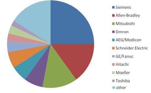
By 1993, Siemens had overtaken Allen-Bradley with about 25% of the world market. AllenBradley was still first in the US but the market had globalized. Mitsubishi was third and Omron fourth. Modicon had been purchased by AEG and was still in fifth place. Texas Instruments was now part of Siemens as purchases of controls companies by other controls companies intensified. See Fig. 1-5 below:
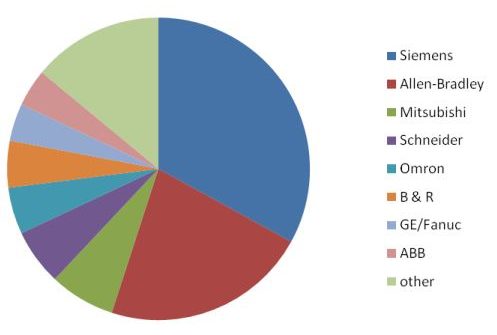
Since 1992, Siemens has continued its place as number one and widened its lead somewhat. Allen-Bradley continues in a strong second place. One company not known for its PLC entry appeared in the 2007/2008 market survey – ABB. ABB is a very strong controls company in the world and had been absent from earlier surveys but appears on this analysis although in a small position overall.
Choice of a PLC must include Siemens as well as Allen-Bradley for the US market. Siemens’ strength can be seen in its attention to detail and its global strategies. One should thoroughly study the languages found in the Siemens PLCs in order to write logic for the world market. STL (Statement List) should be learned as well as LAD (Ladder) and FBD (Function Block Diagram). It is not enough to insist only on LAD with an occasional subroutine written in FBD or other language.
Choosing a PLC [5]
Programming of the first programmable controllers
To those involved in Europe and the US, it was clear from the start that, to be widely accepted, programmable controllers would also have to be easily programmable by skilled workers, electricians, installation engineers, and manual workers – not just by expert programmers. It was important to meet the target groups on familiar territory with regard to their existing level of technical know-how.
The plant electrician could, of course, read circuit diagrams. Engineers were somewhat familiar with Boolean algebra or could easily learn it. And young people who already know how to use progamming languages could quickly learn how to use menmonic instructions.
These basic programming languages had asserted themselves relatively quickly, and these are now defined in the global standard IEC 51131.1: Ladder diagram, function block diagram and statement list resp. instruction list.
Siemens had at first used STL programming exclusively and been very successful with it. It seemed reasonable to program something in the way people think of it and describe it verbally. High education standards in Germany and Europe also supported this approach.
In the USA, where training for skilled workers was generally less intensive than in other countries, the ladder diagram, derived from the circuit diagram, dominated from the start.
To study the Siemens PLC in the US, one must recognize a change in attitude that the European worker has accepted for a much longer time – that programming must be flexible and written in the language best suited for the application. The American student must follow the rigors of the STL or SCL and FBD languages as well as LAD in order to successfully compete in the marketplace today. We must accept the challenge of the quote above and be diligent in mastery of the PLC and all its various languages and hardware. We must not accept the idea that PLCs are for only the technician or electrician but rather for all levels of technical personnel. Multiple languages and multiple platforms must be the goal of anyone studying the PLC and its use in automation.
IEC 61131-3
IEC 61131-3 was intended to achieve the long-term aim of creating user software largely vendor independent and being able to port it to devices of difference to system integrators who want to use different target systems. The chart below compares Allen-Bradley, Siemens and the IEC 61131-3 international PLC language:
| Table 1-3 PLC Languages | |||
| Allen-Bradley RSLogix | Siemens Simatic | IEC 61131-3 | |
| Ladder / Relay Ladder | LAD / Ladder Diagram | LD / Ladder Diagram | Based on circuit diagram |
| FBD / Function Block Diagram | FBD / Function Block Diagram | FBD / Function Block Diagram | Based on switching circuit systems |
| SFC / Sequential Function Chart | S7-Graph for sequencers | SFC / Sequential Function Chart | For sequential control |
| S7-HiGraph Statetransition diagrams | For asynchronous processes | ||
| CFC / Continuous Function Chart | In the form of technology oriented diagrams | ||
| STL / Statement List | IL / Instruction List | Similar to assembler | |
| ST / Structured Text | S7-SCL / Structured Control Language | ST / Structured Text | Pascal-like high-level language |
Exercises
An article by Jeremy Pollard expands more thoroughly what IEC 611131-3 is and what the benefits are. While this topic is beyond the scope of an introductory chapter, this seemed to be the only place to include it.
- IEC 61131-3 by the Numbers by Jeremy Pollard. Published May 2011 in Control.
Other Topics Close to PLC’s
Topics of interest in a PLC text in addition to programming languages should include:
- Distributed I/O
- Fabrication of a system including the cabinet, lay-out, drawings
- Fault tolerant/safe systems
- RS485 networks including Profibus and DeviceNet, simple protocols and simple ASCII
- Use of HMI (Human Machine interface)
- Ethernet networks, wireless
- Relation between PLC and CNC and PCS (DCS), robotics
- Sensors and actuators
- Batch Systems
- MES (Manufacturing Execution System) to include
- Business Modeling Factory
- Enterprise Asset Management
- Plant Maintenance Management
- Dispatch
- Trace and Tracking
- ERP(Enterprise Resource Planning) (or how to make it all work together)
While not each topic will be discussed in detail, the purpose of the text is to include as much about each of these topics as possible. Some topics that are not included but should be of interest to the control engineer include:
- Chemistry
- Fluid Flow (sizing of valves, pumps, pipes)
- Statics and Dynamics (sizing of servo systems, motors, etc)
- Local area networks, wide area networks
- Database development
- Automatic Control – modeling using statistical methods and dif eq
- Machine Design
Each of these areas may be of interest to the student but will not be discussed in detail in this text.
Summary
The emphasis is on programming with LAD and other languages in the most efficient manner to compete in the world marketplace. While hardware will not be emphasized, its use and inclusion in any text is necessary.
The following picture is from a Siemens school in Germany in 2008. These are instructors from around the world for PLCs. I was there but not in the picture.
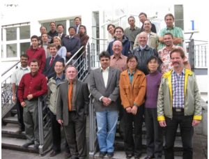
This school was sponsored by Siemens and included PLC instructors from around the world. There were 19 from China, about 7 from Eastern Europe and former Soviet republics, 7 from Mexico and South America. There were none from Western Europe. None from Japan or Korea.
There was one from Malaysia. There were four from the US. Two were covering a start-up for a Mercedes Benz auto plant moving into Spartanburg, SC. There was one other, a salesman, and myself. I was the only one from the US who was just there trying to figure out what to do with the Siemens PLC and how to add it to the educational offering at my school. I often have wondered how the various persons at this school are doing, if they went back to their respective school and are teaching the Siemens PLC. I do not know. I do know that the Chinese were very good at getting the lab exercises done. I never bested them by getting one done first. They were always the first to get the project to work (get the part to move, etc).
The following obituary may be read in full online. I include only highlights:
Engineering Community Remembers PLC Inventor Dick Morley
Morley, who died in October 2017, was revered as much for his ingenuity as for his modesty and the encouragement and mentorship he provided other engineers. REBECCA ZUMOFF — DECEMBER 19, 2017
“Dick Morley wasn’t just the inventor of modern-day automation-he was also a mentor and a friend to many of our members and leaders around the world,” said International Society of Automation President Steve Pflantz in a written statement. “He was a one-of-a-kind person, someone you could never forget. His humor and wit, along with his incredibly creative way of looking at life, made him a force for good in our industry, our society, and the world. He will be missed.”
“When we first met at a trade show many years ago, I praised Dick, the inventor of the PLC, for being the reason any integrators have a job at all. ‘Oh, I didn’t invent it,’ I remember him responding. ‘That was just an idea whose time had come, and I just happened to be the guy working on it,”’ Rick Caldwell, president and founder of SCADAware wrote in an article after Morley’s passing. Caldwell considered Morley a mentor, and said he came up with the name SCADAware.
“We know that one of the most important parts of Morley’s life was his work with young people,” Pflantz said in the scholarship announcement. “He was passionate about giving kids a chance to innovate, to redefine their lives, and to make a difference in the world. We intend to make sure that this scholarship fund continues that legacy in some small way.”
- Brodzik, R. (2014, August 27). Inside the competition for the first PLC . Comtrol Engineering. https://www.controleng.com/articles/inside-the-competition-for-the-first-plc/ ↵
- Table 6.5b from Process Control by Liptak ↵
- Process Control by Liptak ↵
- Milestones in Automation (pg 154) by Arnold Zankl ↵
- from Milestones in Automation by Arnold Zankl – Siemens: (pg 53-54), ↵
new defintion
