
12 Handling Data
Introduction
In this chapter are found a number of output commands that handle data. These are instructions that tend to be accepted with most PLC manufacturers as a core of instructions that accomplish a simple task and provide a useful function to the larger program.
These instructions include boolean instructions, instructions for handling simple math conversions, file manipulation instructions, queuing instructions, and instructions for bit shifting.
Many of these instructions were created after earlier PLCs reported some functions being performed again and again at the cost of a great amount of PLC code. For instance, the queuing operations of FIFO or LIFO could be created in PLC code using a number of other instructions. This became too confusing to the PLC programmer and the FIFO or LIFO instruction was provided as a result.
Some of the instructions came about as the result of the PLC emulating the microprocessor instruction set. Word-length boolean instructions such as AND and moving operations such as bit shifting were copied and installed in the PLC instruction set from similar microprocessor instructions.
The most important point of the chapter is that most instructions are given with an example from industry. Each of these examples has been programmed by many different programmers using techniques similar to the examples shown. Instructions such as these have been used to provide control of automation for a wide variety of industry and solve many complex problems.
Siemens Word Logic and Shift/Rotate Instructions
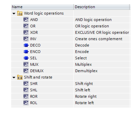
Instructions from Siemens are given first. They are word logic operations and shift/rotate instructions. The instructions are shown in the groups below and their operations are explained in the following pages.
These instructions are covered in the following with the instruction definition given followed by, in many cases, an example. The instructions may be further described by using the ‘help’ menu while in the programming menu on the TIA portal.
AND
“You can use the AND logic operation instruction to combine the value at the IN1 input and the value at the IN2 input bit-by-bit by AND logic and query the result at the OUT output. When the instruction is executed, bit 0 of the value at the IN1 input and bit 0 of the value at the IN2 input are logically ANDed. The result is stored in bit 0 of the OUT output. The same logic operation is executed for all other bits of the specified values.”
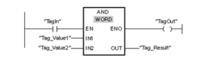
The following table shows how the instruction works using specific operand values:
| Parameters | Operand | Value |
| IN1 | Tag_Value1 | 0101 0101 0101 0101 |
| IN2 | Tag_Value2 | 0000 0000 0000 1111 |
| OUT | Tag_Result | 0000 0000 0000 0101 |
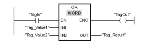
OR
“You can use the OR logic operation instruction to combine the value at the IN1 input and the value at the IN2 input bit-by-bit by OR logic and query the result at the OUT output. When the instruction is executed, bit 0 of the value at the IN1 input and bit 0 of the value at the IN2 input are logically ORed. The result is stored in bit 0 of the OUT output. The same logic operation is executed for all bits of the specified tags.”
The following example shows how the instruction works:
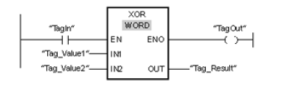
XOR
“You can use the EXCLUSIVE OR logic operation to combine the value at the IN1 input and the value at the IN2 input bit-by-bit by EXCLUSIVE OR logic and query the result at the OUT output.”
The following example shows how the instruction works:
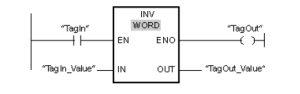
INV
“You can use the Create ones complement instruction to invert the signal state of the bits at the IN input. When the instruction is processed, the value at the IN input and a hexadecimal template (W#16#FFFF for 16-bit numbers or DW#16#FFFF FFFF for 32-bit numbers) are logically EXCLUSIVELY ORed. As a result, the signal state of the individual bits is inverted and sent to the OUT output.
The instruction is only executed if the signal state is 1 at the EN enable input. In this case, the
ENO output also has the signal state 1.”
The following example shows how the instruction works:
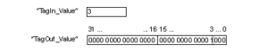
“You can use the Decode instruction to set a bit in the output value specified by the input value. The Decode instruction reads the value at the IN input and sets the bit in the output value whose bit position corresponds to the read value. The other bits in the output value will be overwritten with zeroes. When the value at the IN input is greater than 31, a modulo-32 instruction is executed.”
The following example shows how the instruction works:
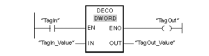
The following figure shows how the instruction works using specific operand values:
ENCO
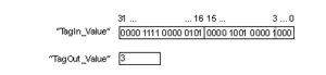
“You can use the Encode instruction to read the bit number of the least significant bit in the input value and to send it to the OUT output. The Encode instruction selects the least significant bit of the value at the IN input and writes its bit number to the tag in the OUT output.”
The following example shows how the instruction works:
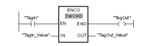
The following figure shows how the instruction works using specific operand values:
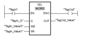
SEL
“Depending on a switch (G input), the Select instruction selects one of the IN0 or IN1 inputs and copies its content to the OUT output. When the G input has the signal state 0, the value at the IN0 input is moved. When the G input has the signal state 1, the value at the IN1 input is copied to the OUT output.”
The following example shows how the instruction works:
The following table shows how the instruction works using specific operand values:
| Parameters | Operand | Value | |
| G | TagIn_G | 0 | 1 |
| IN0 | TagIn_Value0 | W#16#0000 | W#16#4C |
| IN1 | TagIn_Value1 | W#16#FFFF | W#16#5E |
| OUT | TagOut_Value | W#16#0000 | W#16#5E |
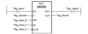
MUX
“You can use the Multiplex instruction to copy the content of a selected input to the OUT output. The number of selectable inputs of the instruction box can be expanded. The inputs are automatically numbered in the box. Numbering starts at IN0 and continues consecutively with each new input. You use the K parameter to define the input whose content is to be copied to the OUT output. If the value of the K parameter is greater than the number of available inputs, the content of the ELSE parameter is copied to the OUT output and the ENO enable output is assigned the signal state 0.”
The following table shows how the instruction works using specific operand values:
| Parameters | Operand | Value |
| K | Tag_Number | 1 |
| IN0 | Tag_Value_0 | DW#16#00000000 |
| IN1 | Tag_Value_1 | DW#16#3E4A7D |
| ELSE | Tag_Value_2 | DW#16#FFFF0000 |
| OUT | Tag_Result | DW#16#3E4A7D |
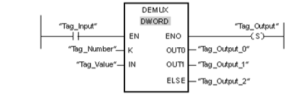
DEMUX
“You can use the Demultiplex instruction to copy the content of the IN input to a selected output. The number of selectable outputs can be expanded in the instruction box. The outputs are automatically numbered in the box. Numbering starts at OUT0 and continues consecutively with each new input. You use the K parameter to define the output to which the content of the IN input is to be copied. The other outputs are not changed. If the value of the K parameter is greater than the number of available outputs, then the content of the IN input will be copied to the ELSE parameter and the signal state 0 is assigned to the ENO enable output.”
The following example shows how the instruction works.
The following table shows how the instruction works using specific operand values:
Input values of the Demultiplex instruction before network execution:
| Parameters | Operand | Values | |
| K | Tag_Number | 1 | 4 |
| IN | Tag_Value | DW#16#FFFFFFFF | DW#16#3E4A7D |
Output values of the Demultiplex instruction after network execution:
| Parameters | Operand | Values | |
| OUT0 | Tag_Output_0 | Unchanged | Unchanged |
| OUT1 | Tag_Output_1 | DW#16#FFFFFFFF | Unchanged |
| ELSE | Tag_Output_2 | Unchanged | DW#16#3E4A7D |
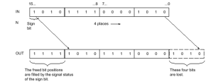
SHR
“You can use the Shift right instruction to shift the content of the operand at the IN input bit-by-bit to the right and query the result at the OUT output. You use the N parameter to specify the number of bit positions by which the specified value is to be shifted.”
The following figure show how the content of an operand of integer data type is shifted four bit positions to the right:
The following example shows how the instruction works:

The following table shows how the instruction works using specific operand values:
| Parameters | Operand | Value |
| IN | TagIn_Value | 0011 1111 1010 1111 |
| N | Tag_Number | 3 |
| OUT | TagOut_Value | 0000 0111 1111 0101 |
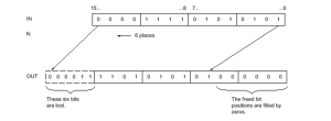
SHL
“You can use the Shift left instruction to shift the content of the operand at the IN input bit-by-bit to the left and query the result at the OUT output. You use the N parameter to specify the number of bit positions by which the specified value is to be shifted. When the value at the N parameter is 0, the value at the IN input is copied to the operand at the OUT output.”
The following figure shows how the content of an operand of WORD data type is shifted six bit positions to the left:
The following example shows how the instruction works:
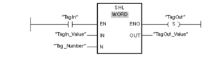
The following table shows how the instruction works using specific operand values:
| Parameters | Operand | Value |
| IN | TagIn_Value | 0011 1111 1010 1111 |
| N | Tag_Number | 4 |
| OUT | TagOut_Value | 1111 1010 1111 0000 |
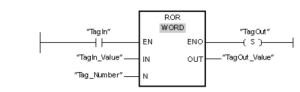
ROR
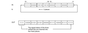
“The Rotate right instruction rotates the content of the operand at the IN input bit-by-bit to the right and queries the result at the OUT output. You use the N parameter to specify the number of bit positions by which the specified value is to be rotated. The bit positions freed by rotating are filled with the bit positions that are pushed out.”
The following figure shows how the content of an operand of DWORD data type is rotated three positions to the right:
The following example shows how the instruction works:
The following table shows how the instruction works using specific operand values:
| Parameters | Operand | Value |
| IN | TagIn_Value | 0011 1111 1001 0101 |
| N | Tag_Number | 5 |
| OUT | TagOut_Value | 1010 1000 0111 1100 |
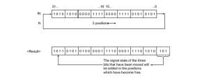
ROL
“The Rotate left instruction rotates the content of the operand at the IN input bit-by-bit to the left and queries the result at the OUT output. You use the N parameter to specify the number of bit positions by which the specified value is to be rotated. The bit positions freed by rotating are filled with the bit positions that are pushed out.”
The following figure shows how the content of an operand of DWORD data type is rotated three positions to the left:
The following example shows how the instruction works:

The following table shows how the instruction works using specific operand values:
| Parameters | Operand | Value |
| IN | TagIn_Value | 1010 1000 1111 0110 |
| N | Tag_Number | 5 |
| OUT | TagOut_Value | 0001 1110 1101 0101 |
