
3 PLCs and Processing I/O
Introduction
After an introduction of PLCs in chapter one, various characteristics of the PLC need to be discussed. The purpose now is to discuss what parts constitute a modern PLC and how these parts interface. The topology of a PLC system is also discussed as to how PLCs are distributed in a manufacturing environment to best control a process efficiently.
Since each is electronic and operates using one or more microprocessors, a 5 volt power supply and CPU (central processing unit) are the core of the PLC. Included in the CPU is a computer with memory and communications hardware to communicate to a programming panel, the I/O, and to a network which is either peer-to-peer or a multimode network.
Many PLC vendors divide the work of the PLC between multiple microprocessors with coordination handled by a master microprocessor. One processor may be assigned to handle the I/O. Another may handle the networking and communication to the programming panel. A supervisory microprocessor handles the logic, scan, arithmetic, and other instructions solution of the program.
Inputs and outputs complete the PLC with inputs reporting the status of the system and outputs controlling the sequencing of the process. Inputs and outputs are of many types and forms. A simple switch can be an input. Also, a high-speed pulse input can be an input providing speed information from a motor. Inputs and outputs alike can be simple or complex in nature. Both the simple I/O as well as the more complex will be discussed in the chapter and through the rest of the book.
Overview of the PLC
Inputs form the portion of the PLC connecting switches, sensors, transducers and other devices to the processor. Typically, the input is tied to a screw terminal. The PLC program reads the status of the inputs and solves logic based on this status.
The CPU stores the program and controls communication with all peripherals including programming devices as well as the I/O. The CPU executes the programs in an orderly manner and guarantee that I/O responds per the program. The guarantee is not trivial if one is experienced with most computer operating systems.
Outputs are connected to devices that control the process. Relays, motors, solenoids and other outputs are some examples. A pulse wave PWM is one that controls stepper motors and positional movement. The PLC program can control the status of this output and thus control the motor speed and movement.
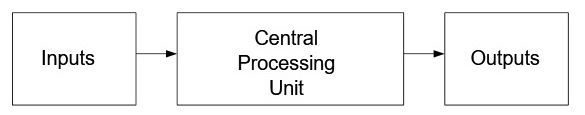
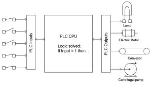
In the figures below, the simplified PLC is shown first followed by an expanded view of the PLC. Each view shows the importance of the CPU (Central Processing Unit) as well as the interconnection of the CPU to I/O (Inputs and Outputs). Other devices interact in such a way that the program executes and solves logic in a timely manner.
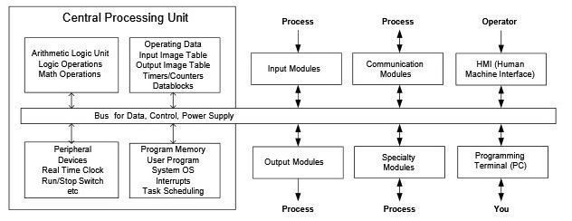
The second view gives a greater detail of data flow into and out of the PLC. As the devices and programs become more involved, the flow of data must both increase while being as secure as with simple systems. All systems may not use communication modules or specialty modules. Some may use a great number. All will use some kind of programming terminal and “you” will be responsible for providing the program to run it.
Most PLCs also have a table reserved for health status of the cpu, the I/O, and the software. This table can be monitored to find if processor errors have occurred. Status tables may be ignored for the most part until something goes wrong. When an error occurs, their use is extremely important to the programmer and to the recovery of the processor. The programmer must monitor the status table in order to determine what went wrong and to restore the processor to running condition again.
Also along-side the PLC’s cpu is a watch dog timer (WDT). The WDT monitors health throughout the PLC and shuts down the I/O and program if there is a danger that the program or hardware has caused a major breakdown of the PLC’s integrity to process the program and control the process. The WDT is helpless to shut down the machine being controlled if the program in the PLC is not functioning correctly due to poor programming. Care must be taken to consider all possible conditions of a program. The proper control of the machine or process under all conditions and circumstances is critical.
What Happens Electrically
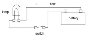
Figure 3-2 demonstrates the flow of current in a simple circuit. The battery provides power to the lamp but is blocked in Fig. 3-2b because the switch is open. With an open switch, no current flows and the circuit is incomplete. When the switch closes, however, current flows and the lamp is illuminated (Fig. 3-2c). As simple as this circuit is, it contains the fundamental principle of input and output flow in a control circuit and the PLC.

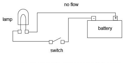
The schematic for these circuits resembles the circuit below (Fig. 3-2d). Symbols have replaced their physical devices but the functionality remains the same.
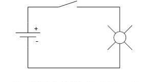
Fig. 3-3 shows the PLC solving logic in a similar manner to the simple circuit above. The complication of additional circuits solving logic adds to the sophistication of the circuit. This allows much more sophistication in the defining of how a circuit will perform under all conditions.
In addition to simple PLC networks such as that above, the PLC may contain network I/O allowing inputs and outputs to be communicated with at remote locations. Fig. 3-5 demonstrates this type of system.
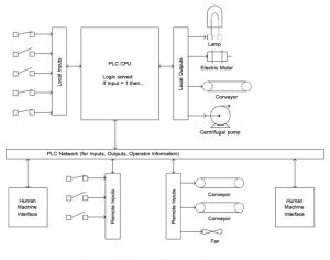
Inputs and outputs may even be communicated over wireless networks and this type of network is becoming increasingly more popular as wiring costs continue to rise and the equipment is designed for safe operation in all environments. Safe wireless networks are the latest advances in PLC equipment and offer expansion of logic into areas formerly off-limits to the PLC.
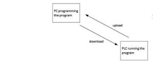
The PLC program is generated on a PC using the manufacturer’s software, and temporarily stored there.
After the PC is connected with the TCP/IP interface of the PLC, the program can be transferred with a load function to the PLC’s memory.
The PC is no longer needed for further program processing in the PLC except to monitor the online program observing the operation of the inputs, outputs and logic (program) linking the inputs to the outputs.
The Generic PLC
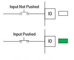
How does the PLC replace relay logic from a ladder logic diagram? Consider the following example. Pictured below is a simple generic PLC with four inputs and four outputs. One input is wired to a push button and one output is wired to an indicator light. While not exactly the same as our PLC processor, the steps of installing a program and wiring the PLC are the same.
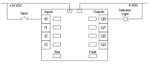
Notice when wiring an input and energizing the button that the green indicator light for the input comes on:
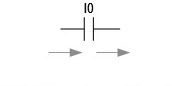
In the program, contacts referring to the input conduct as shown below:
The program needed to create a circuit similar to the switch and light of Fig. 3-2d is shown below:
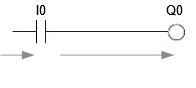
and the Run light is on: Run
then the output will turn on and the light will turn on.
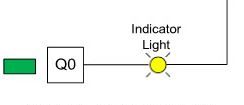
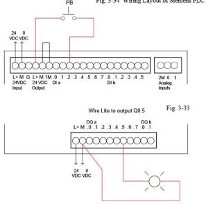
When the program shows the output on, the output LED turns on and the output terminal energizes the light as shown:
When the program is turned from Run to Program, the output LED turns off and the output turns off. The outputs also turn off and the Run light goes off if a fault occurs.

How is the Program Processed in the PLC?
The program is processed in the PLC cyclically, in the following sequence:
- First, the status is transferred from the process image of the outputs to the output terminals.
- The processor examines the individual inputs for high voltage or low voltage. Status of the inputs is stored in the process image of the inputs. For the inputs with the rated voltage a 1 or HIGH is stored, for those that don’t the 0 or LOW is stored.
- This processor then processes the program stored in the program memory. The program consists of a list of logic operations and instructions that are processed one after the other. For the required input information, the processor accesses the input table entered previously and the result of the logic operation is written into a process image of the outputs. If necessary, the processor also accesses other memory areas during program processing; for example, for local data of sub- programs, data blocks and flags.
- Then, internal operating system tasks such as self-tests and communication are performed Then we return to item 1.
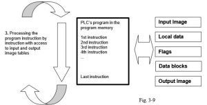
- Transfer the status from the output image to the outputs
- Store the status of the inputs in the input image table
- Processing the program instructions with access to input and output image tables
- Perform internal operating system tasks (communication, self-test, etc…)
Note: The time the processor needs for this sequence is called cycle time. In turn, the cycle time depends on the number and type of instructions and the processor capacity.
I/O
We need to discuss the types of inputs and outputs that constitute a valid PLC system. For inputs, we find:
Input Systems[1]
Inputs are defined as real-world signals giving the controller real-time status of process variables. These signals can be analog or digital, low or high frequency, maintained or momentary. Typically they are presented to the programmable controller as a varying voltage, current, or resistance value.”
Analog signals include thermocouple and resistance temperature devices. Digital signals include on-off signals from relay contacts or push buttons. Signals such as flowmeters provide frequency input with the frequency varying with the flow.
Signals to the programmable controller are input from single wire devices or from parallel signals. A thumb-wheel switch or scale system can input a four-digit number from four BCD parallel digits. Many signals such as the scale system also require a synchronization signal before data can be read.
Inputs include the following types or attributes:
- DC voltage
- AC voltage, ranges of 50 Hz or 60 Hz available
- True High or True Low DC voltages
- Analog inputs, ranges 0-10V or 4-20 ma most popular BCD, Binary Coded Decimal
- Thermocouple
- Scale/load cells/LVDT, weight and force sensors RTD, Resistance Temperature Detector Latching
- Isolated or Common Neutral
- Intelligent (Smart with own CPU on board I/O card) Resolver
- Encoder
- Serial Communications Port
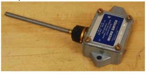
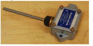
An example is the limit switch shown below:
Outputs[2]
There are three common categories of outputs: discrete, register, and analog. Discrete outputs can be pilot lights, solenoid valves, or annunciator windows (lamp box). Register outputs can drive panel meters or displays; analog outputs can drive signals to variable speed drives or to I/P (current to air) converters and thus to control valves.”
Output signals are similar to input signals in that signals can be either analog or digital. Digital signals can be either single data or a parallel arrangement of bits. Most modules are ordered in arrangements of 4, 8, 16, or 32 devices per card.
Both input and output signals are optically isolated in designs for the US market. This protects signals from entering the interior of the PLC and allows the designer to wire circuits less carefully than in circuits without optical isolation. One main design difference between US and European PLC design is the lack of optical isolation in the European design.
Outputs include the following types or attributes:
- DC voltage
- C voltage, ranges of 50 Hz or 60 Hz available
- Isolated or Common Source
- True High or True Low DC voltages Analog Output
- Serial Communications Port
- Intelligent (Smart with own CPU on board I/O card) Servo Controller
While I/O modules vary in type and number, recent developments have caused even these general rules to change. Distributed I/O is an example of a small number of inputs and outputs isolated at a machine that control a portion of a machine remotely from the PLC. Typical remote I/O requires a rack, power supply and a large number of cards while distributed I/O is pre-configured for only a small number of inputs and outputs. A number of advantages occur with the use of distributed I/O in that the machine can be wired and tested in one facility, broken down and shipped to a second facility, and re-connected with very little change in the wiring.
This leads to quicker start-ups and cheaper overall wiring costs. Typical distributed I/O is controlled over a communications network that is daisy-chained from device to device.
Some examples of PLC outputs include:
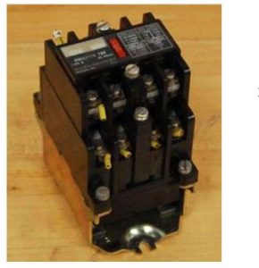
The relay pictured may provide input contacts but is primarily used to turn on or off various other signals from the PLC and is connected to a PLC output to accomplish this task.
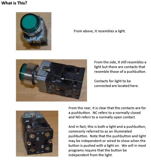
What is This? — replace images below – screenshot with out text
Looking ahead in Chapter 5, we have an example of an Input/Output table. This table is organized to define the type of sensor or actuator, its function and the signal assignment. Signal assignments are made based on the condition of the program if the signal is compromised. If a wire falls off and the program responds poorly, then the signal assignment should be changed to the opposite type. Signal assignment of 1 is referenced as Normally Open and 0 referenced as Normally Closed.
The table below may be expanded to include the I/O address, ordering information, cost, and other pertinent information. This table has many uses and is important to the overall project’s success.
| Sensor | Function/State | Signal Assignment |
|---|---|---|
| Start Button | Start | 1 |
| High Level Switch | Level Exceeded | 0 |
| Half Level Switch | Level Exceeded | 1 |
| Temperature Switch | 80° C Exceeded | 0 |
Table 3-1 Input Definitions
| Actuator | Function/State | Signal Assignment |
|---|---|---|
| Agitator Motor | Stirring/Running | 1 |
| Fill Valve V-2 | Fill Tank | 1 |
| Flush Valve V-1 | Empty Tank | 1 |
| Heat | Heat Juice | 1 |
| Done/Ready Indicator | Illuminated | 1 |
Table 3-1 Output Definitions
How to Run a PLC Program
The steps to run a program in the plc is common to all plc manufacturers. It in general follows the following steps:
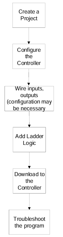
Next we study the major brands of PLCs and begin the process of setting them up for use as a relay simulator and much more. This is the study of how to program a process and the PLC can do so much more than relays could. This is part of what will be explored.
The SIMATIC S7-1200
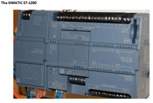
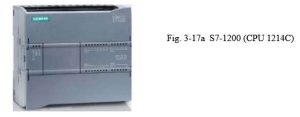
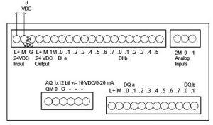
Pictured below is a S7-1200 PLC from Siemens. It is a powerful new controller with many capabilities only available in more expensive models until recently.
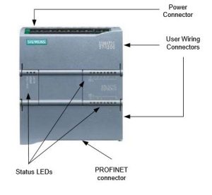
The S7-1200 is referred to as a micro PLC and is programmed in STEP 7 Basic, the newest software offering from Siemens. The processor has capabilities of adding additional I/O to the basic unit shown above. The processor communicates to a programming panel through an Ethernet port referred to as the PROFINET interface found on the bottom of the unit. This port offers access to other controllers, a programmer’s console and various HMI (Human Machine Interface) units.
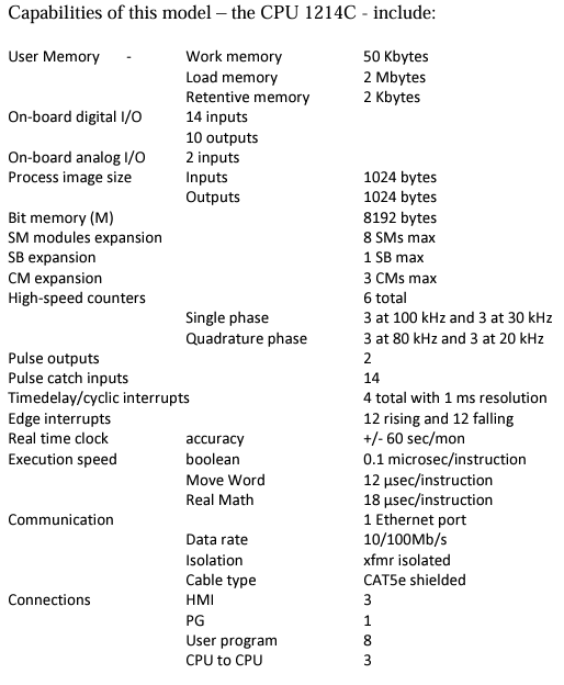
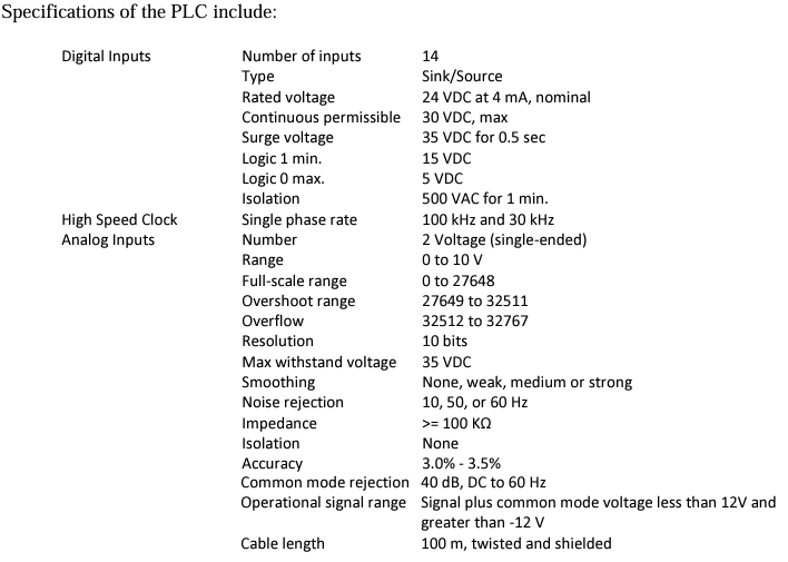
Capabilities of this model – the CPU 1214C – include:
Descriptions of S7-1200 Modules
Central modules CPU with different capacity, integrated inputs/outputs and PROFINET interface (for example, CPU1214C)
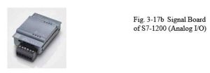
- Signal boards SB for adding analog or digital inputs/outputs; whereby the size of the CPU does not change
(signal boards can be used with the CPUs 1211C/1212C and 1214C)
- SIMATIC memory cards 2MB or 24MB for storing program data and simple CPU replacement for maintenance
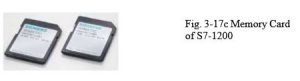
Note: For this module M01, any CPU with integrated digital inputs and digital outputs is sufficient.
The SIMATIC Memory Card (MC) stores the program, data, system data, files and projects. It can be used for the following:
- Transferring a program to several CPUs
- Firmware update of CPUs, signal modules SM and communication modules CM
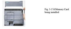
You may want to have this card on hand when you upgrade your software since the version of firmware onboard the PLC must be upgraded at the same time or you may be unable to properly link the PLC to the software in the programming terminal.
Allen-Bradley’s CompactLogix L23E Programmable Automation Controllers
The following processor is the 1769-L23E-QBFC1B:
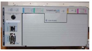
CompactLogix programmable automation controllers (PACs) offer the benefits of the Logix Control Platform—common programming environment, common networks, and common control engine—in a smaller footprint for machine-level control applications. The new CompactLogix L23 extends these benefits into even smaller applications. The CompactLogix L23 controllers include the Logix control engine, power supply and two of the most common I/O configurations, lowering costs and simplifying configuration. Each CompactLogix L23 PAC offers 512Kb of memory, up to three tasks, four programs and embedded EtherNet/IP capabilities for ease of use. Up to two local Compact I/O or communication cards can also be added for additional flexibility.
| 1769-L23E-QBFC1B | |
|---|---|
| Embedded Communication Ports | Isolated Serial (DF1 or ASCII) Ethernet/IP with (MSG + I/O) |
| EtherNet/IP Connections | 8 TCP/IP – 32 CIP |
| Memory | 512 KB |
| Embedded I/O | 16 DC in, 16 DC out, 4 Analog in, 2 Analog out, 4 High-Speed Counters (250 kHz) |
| Expansion | 2 Additional 1769 I/O Modules or 1 1769 Communication Module |
| Tasks | 3-Continuous, Periodic or Event |
| Programs | 4 |
| Routines | Unlimited |
| Languages | LD, FBD, ST, and SFC |
| Alarms & Events | Supported |
| Phase Manager | Supported |
| Add-on Instructions | Supported |
| Dimension | 130x293x90mm |
| Power Requirements | 19.2 – 31.2 VDC – 50VA |
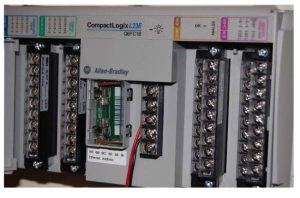
CompactLogix L16ER and the newer S7-1200 Processors
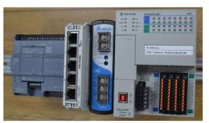
Allen Bradley’s CompactLogix 5370 controllers expand the scalability of the Logix family of controllers, offer a wider variety of options, and provide best-fit alternatives for your specific application requirements. Coupled with Kinetix® 350, the controllers provide high performance in a compact and affordable integrated motion package for a variety of machine applications, all on one common network – EtherNet/IP. The L16ER Compact Logix processor, part of this family is shown above along with the newer Siemens S7-1200 processor. While the Siemens processor is similar to the earlier one, the A-B processor is very different. Some of the characteristics of this processor are:
The CompactLogix 5370 system provides:
- Two EtherNet/IP ports
- One USB port
- Support for local expansion modules
- Control of local and distributed I/O modules
- Use of 1784-SD1 or 1784-SD2 secure digital (SD) card for nonvolatile flash memory
- Internal energy storage solution eliminating the need for a battery
Characteristics
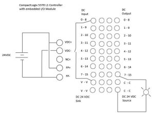
The CompactLogix 5370 L1 controller comes with a built-in 24V DC power supply and embedded digital I/O (16 DC inputs, 16 DC outputs). Up to eight 1734 POINT I/O expansion modules are supported. The following list the characteristics of this processor:
| Characteristic | 1769-L16ER-BB1B |
| User Memory | 384kB |
| Secure Digital Memory Card | 1GB (Standard 2GB (Optional) |
| Communication Ports | DualPort Ethernet DLR. USB |
| Embedded I/O | 16 DC Inputs, 16 DC Outputs |
| Module Expansion Capacity | 6 expansion modules and 4 ethernet nodes |
Network
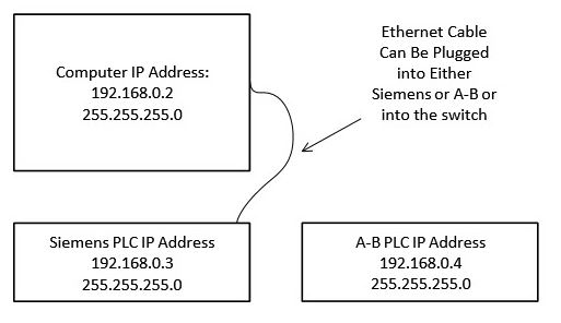
Both A-B and Siemens have various requirements for connecting their processor to the Ethernet cable.
For the PC and the SIMATIC S7-1200 to communicate with each other, it is important that the IP addresses of both devices match.
First, we show you how to set the computer’s IP address.
- From the System control, call the Network connections. Then, select the Properties of the LAN connection (Start ->Settings ->System control ->Network connections->Local Area Connection ->Properties)
- Select the Properties from the Internet Protocol (TCP/IP) (->Internet Protocol (TCP/IP) ->Properties)
- You can now set the IP address and the Subnet screen form, and accept with OK -> Use the following IP address ->IP address: 192.168.0.2 ->Subnet screen form 255.255.255.0 ->OK-> Close)
MAC address
The MAC address consists of a permanent and a variable part. The permanent part (“Basic MAC Address”) identifies the manufacturer (Siemens, 3COM, …). The variable part of the MAC address differentiates the various Ethernet stations and should be assigned uniquely world-wide. On each module, a MAC address is imprinted specified by the factory.
IP Address
Value range for the IP-address:
The IP address consists of 4 decimal numbers from the value range 0 to 255, separated by a period. For example, 141.80.0.16
Value range for the subnet:
The subnet screen form consists of four decimal numbers from the value range 0 to 255, separated by a period. For example, 255.255.0.0
Example:
You entered the following: for the subnet screen form 255.255.255.0, for the IP address
141.30.0.5.
For setup of the A-B IP address, their BOOTP instructions on the internet give a good layout. Once the instructions for setup have been completed, the IP address is easily found using RSLinx Classic.
Once the hardware of an automation system is defined, the next step in the project cycle is to create a program. But before you start programming, it helps a whole lot if you understand the basic “structure” of the S7 PLC. This section will provide the necessary details of the CPU memory model, address areas and uses, how to add elements to a program, program structure, and what tools are available within the program editor for testing.
For our systems, the following local area network has been set up and will allow communication between PLCs and the computer:
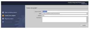
Starting a Project and Logging onto the S7-1200
First, find the TIA V14 Button and click:

View the following:

Select a name of your project. Be aware that you will need to address the project from the H drive or from a stick drive.
Additional instruction is found on the video accompanying this text. Since the instructions vary from processor to processor, please view this video as a first step in logging on and programming the Siemens program.
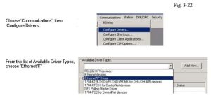
Starting a Project and Logging onto the L23E-QBFC1B and L16ER Processors
First, use RSLinx to configure the EtherNet/IP Driver:
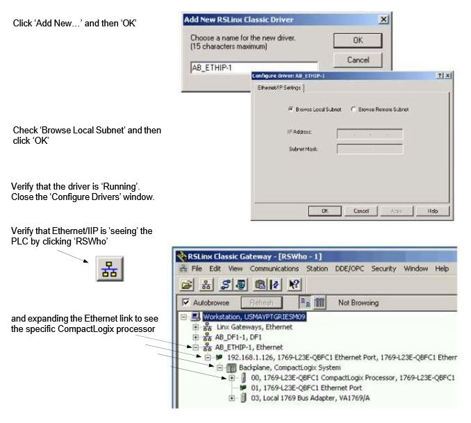
When launching Studio 5000, have the icon on your desktop or launch using Logix software. When launched, the following will appear:

When starting with no program, choose New from the File menu. The New
Controller dialog appears. Choose our controller,
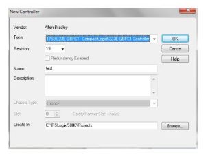
the 1769-L23E-QBFC1 controller, add the revision level, 31 at present, add a
name (text) in this example and click OK
Congratulations! You have a PLC that can do absolutely nothing. There is no tag database and no program stored yet.
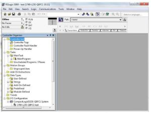
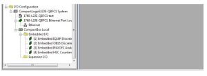
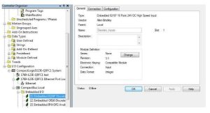
There is, however, an I/O Configuration prepared. It includes the L23E, an Ethernet Port and some Embedded I/O. Note that there is also room for expansion I/O to the right of the processor.
On the left is a tree of folders. These show the controller, its tasks, any trends, data tables and the I/O configuration.
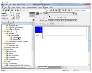
Click MainProgram and then MainRoutine to show the figure below. You are ready to program a rung of logic. Above the MainRoutine logic is the Ladder Instruction toolbar. From this toolbar, you can choose the type of contact to place in the rung of logic.
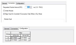
The embedded I/O may need to be configured. For instance, the 16 point input section has the following configuration screens:
It is important that the student practice the programming steps outlined above to be able to start a new project, download a project to the Siemens 1200 PLC and start and stop the processor. The ability to do this will pay dividends in later labs.
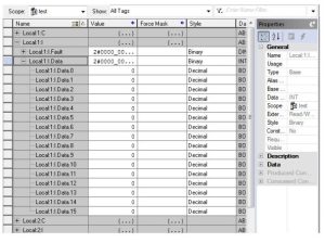
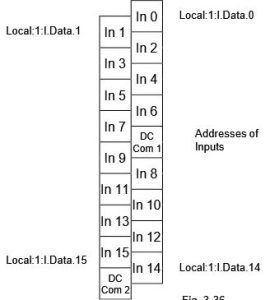
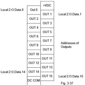
The embedded I/O is addressed automatically in the ‘Controller Tags’ entry. This resembles the following:
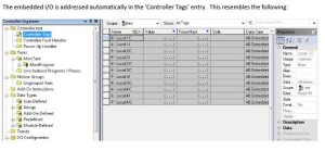
The 16 inputs from the input card section are addressed as follows:
Local:1:I.Data.0 (bit 0)
Again, it is important to view the video for instructions about logging on and programming the A-B.
Wiring the Processor
Both Siemens and A-B require the inputs and outputs be wired properly to have a program accepted as working. Yes, there is a simulator for both but the actual wiring of the project adds a step that most will eventually appreciate the full scope of a PLC project.
Pictured first is a Siemens S7-1200 processor wired for an input and output.
Next is an A-B L23E-QBFC1B processor wired for inputs and outputs:
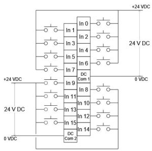
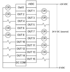
Finally an A-B L16ER processor wired for inputs and outputs:
Operating Modes of the CPU
The CPU has the following operating modes:
- In the operating mode STOP, the CPU does not execute the program, and you can load a project
- In the operating mode STARTUP, the CPU performs a startup.
- In the operating mode RUN, the program is executed cyclically. Projects can not be loaded in the CPU’s RUN mode.
The CPU does not have a physical switch for changing the operating mode. The operating mode (STOP or RUN) is changed by using the button on the operator panel of the software STEP7 Basic. In addition, the operator panel is provided with the button MRES to perform a general memory reset and displays the status LEDs of the CPU.
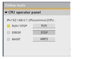
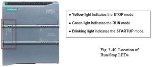
The color of the status LED RUN/STOP on the front of the CPU indicates its current operating mode.
In addition, there are the LEDs ERROR to indicate errors and MAINT to indicate that maintenance is required.
All the processors of Allen Bradley CompactLogix PLC have a key switch of RUN-REM-PROG with the following functionality. Mode of RUN allows no edits. REM PLC in the processor remote mode control allows remote programming with RSLogix 5000. Program mode or PROG PLC will stop the processor and allow downloads
Download vs Upload
The Earliest Programming Panel
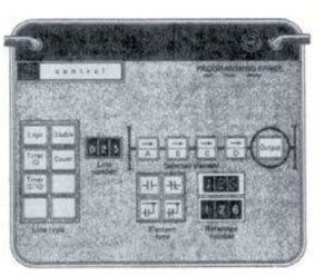
The programming panel above is of the first PLC, the Modicon 084. There was a very limited group of Boolean expressions available for the programmer. All other expressions were required to be broken into a number of rungs that together represented the original Boolean expression.
The four buttons for normally open, normally closed, parallel normally open and parallel normally closed were the only choices. The parallel branches were tied back to the left power bus.
The figure below shows the limited choices for each of the four contacts and how the combinations of these expressions forced the engineer to break up most logic into a number of rungs or lines of logic.
This cryptic first PLC’s restrictions seem very limiting. They are. To be blunt, all PLC’s force the user to make compromises with an original schematic drawing. Electricity flows in any direction but the PLC manufacturers forced power to flow left to right and never in the reverse direction. Power could flow up or down but never right to left. This compromise is still in place with all PLC manufacturers (with ladder). With the FBD programming format, lines can be drawn in any fashion and connections flow in any direction.
I first “cut my teeth” on PLCs at Rochester Products Division of General Motors in Rochester, New York, when I was asked to modify logic in some of its manufacturing machines in 1977. The first one I was given was an in-line machining center that performed drilling and tapping at various angles on automotive carburetor housings in stages. There were 65 stations in this one system controlled by four Modicon 084 programmable logic controllers (PLCs).
If you are not familiar with the 084 PLCs, these dinosaurs had core memory of about 1 k of toroid donuts per card, with one bit per donut; and the logic consisted of four contacts and a coil for every rung. The contacts could be normally open (NO) or normally closed (NC) and could be logically ORed (or not) with the left power rail. It was programmed using a Zero case enclosed programming panel using thumb wheels, push buttons and indicator lights.
We “saved” the programs by calling the central computer room and then connecting the phone to a modem, using a different Zero case, where the computer room would capture the program with a DEC PDP-8 minicomputer and then punch a paper tape for storage on a shelf. We had to hand- draw all of the logic on D-size sheets and update the drawings when the logic was changed.[3]
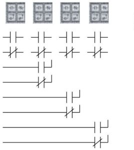
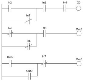
An example program is shown in the figure below showing how the original circuit was broken into a number of simpler circuits following the restrictions outlined above.
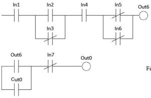
The circuit at above is the circuit required but the programming panel above allows only four contacts and each contact after the first is either NO, NC or parallel NO or NC back to the left power bar.
The circuit above is broken down into the circuits below.
Summary
In this chapter we discuss a number of topics related to starting up a PLC project. This includes the PLC itself, what it is and how it works. Also included is a discussion of I/O, inputs and outputs, the devices that give input to the PLC program and report on the outputs of that program.
A generic PLC helped in this with an illustration of a simple light-bulb circuit and the PLC implementation of that circuit. Simple as that illustration was, it demonstrated all the aspects of describing the PLC equivalent of the original circuit.
The scanning capabilities of the PLC were discussed along with various types of inputs and outputs.
Then we discussed the specific characteristics of the PLCs used in this text. They include the Siemens S7-1200 and the Allen Bradley CompactLogix L23E and L16ER.
We will have the IP addresses and network system already set up for students to use but an introduction to IP addresses, subnet masks and additional information was introduced.
Finally, the starting of the programs was discussed. Most of the internal programming will be discussed in class and through videos. The text is only to be used as an over-view in this case.
Also discussed was the wiring of various inputs and outputs. Each processor has unique requirements in this area and these requirements will need to be addressed for completion of any project.
