Chapter 4 Exercises
Exercises
- *In the program of Fig. 4-53, if input Catsup were changed from a NO contact to a NC contact, how would the program have changed to not change the function of the push button?
- Would the program of Fig. 4-53 be significantly changed if the two N.C. contacts in the third rung were removed?
- Where in the program of Fig. 4-53 could the copy/paste function have been used effectively?
- Name the different processor modes for the Siemens S7-1200, the A-B L23E.
Lab 4.1 The Hot Dog Counter
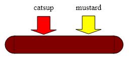
Project Description: Fred and Rudy are making hot dogs at the ballpark. Fred dispenses mustard and Rudy dispenses catsup. A hot dog is not sold without each Fred and Rudy putting both mustard and catsup on the dog. As each pushes the button for their ingredient, a signal is fed to the PLC for the action. Either button may be pushed first. Design a program to count the total number of hot dogs made. Inputs should be wired to contacts and labeled as mustard and catsup. A display is kept in the PLC showing up-to-date counts of hot dogs made by Fred and Rudy.
To complete the lab, enter the program shown later in the lab into the PLC and wire the two inputs.
Watch the count accumulate in the counter as the two buttons are pressed in any order. Get a listing from the listing software on the programming software package.
The documented listing of the program may be used as the final lab report.
Wire the PLC to the inputs for this lab and to inputs or outputs for other labs per the diagram on the next page.
The next page shows the layout of the PLC on the trainer and the PLC wiring schematic. To wire the two inputs, wire through the two pushbuttons selected so that 24 volts is at the terminals
Enter the following 4 rung program in both Siemens TIA Portal and A-B RSLogix 5000.
Download both and wire the inputs. Demonstrate a working counter to your instructor:
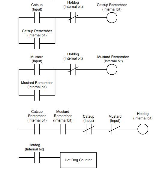
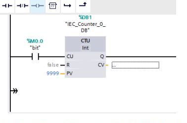
The count of hot dogs made is found in the accumulated value of the counter.
Both PLC platforms have instruction help features which may be used at this point to find how the counter function above is programmed. RSLogix 5000 has this feature in its Help>Instruction Help tab. Siemens has similar help features but has helps with the instruction to identify variable types in the instruction itself.
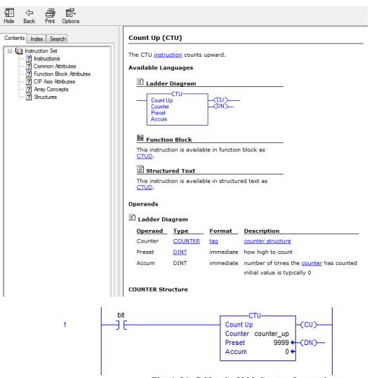
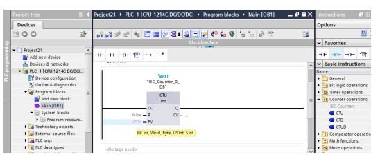
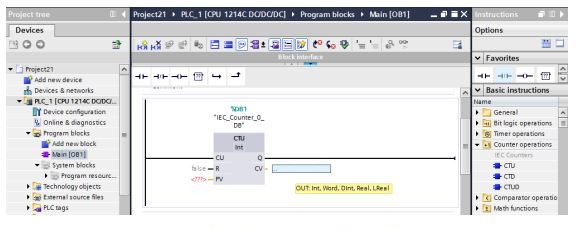
In the example above, Figs. 4-51 and 4-52 show the type of inputs available for PV and CV. In general, PV is short for process variable and CV is short for the controlled variable. For the up- counter, PV is the count preset and CV is the active count. The PV may hold a constant as shown below: