Chapter 7 Exercises & Labs
Exercises
- De-bounce Circuit Leading Edge: Design a de-bounce circuit which will override the bounce of a limit switch on the leading edge only. Allow no input that is not on for at least .5 second. Use Limit_switch_1 as input.
- For the following circuit, answer the questions below:
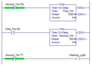
-
- How long does the flashing light stay on?
- How long does the flashing light stay off?
- Modify the circuit so that the output is on for 1.3 seconds and off for 1.2 seconds.
- Modify the circuit so that the output is on for 2.5 seconds and off for 1.7 seconds.
- Design a program that turns on a latch when a button is pushed three times in less than 2 seconds.
- A low pressure switch is to be added to a fan starter circuit. Assign inputs for stop, start and low pressure. If the fan loses pressure, then it is to shut down. Design a start/stop seal circuit that stops on low pressure. Remember that when the fan is off, pressure is low.
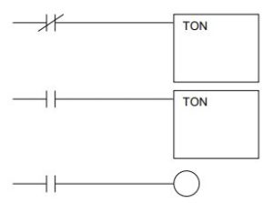
- Complete the following rungs to give a light that flashes on for 1.3 seconds and off for .2 seconds using Siemens’ timers:
 Rewrite the flashing circuit using Siemens FBD, using A-B’s FBD.
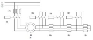
 - To start asynchronous wound motors, resistors are connected in the rotor circuit to avoid a high inrush current. After pushing the start button S1, the line relay is closed. Then relays K2, K3 and K4 are closed, each after a time delay of 5 seconds. Write the program to start M3.
- A group of three motors should be controlled. Each motor is equipped with a revolution monitoring device. If the motor turns, the sensor indicates “1” (otherwise “0”). The switch S1 activates the monitoring circuit. The failure indication (fault) is to light in the following cases:
a. If two of the three motors failed longer than 10 seconds
b. If all three motors failedThe fault light is to stay lit until a reset switch is activated (acknowledged).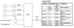
- Count and Time Program: How many parts per minute are going past a certain process point? The counter is pulsed for each part going past the sensor, which is connected to Input 1. The counting begins and the timer starts timing through its 60 second time interval. At the end of 60 seconds, pulses continue but do not affect the counter. The part count for the minute will remain in the counter register until switch S is opened. Then the counter and timer are reset. When S is closed again, another 60 second interval occurs with another part count saved at the end of the 60 second period.
How would you make the process continuous with the last 60 second part count the one read?
How would you make the process show the average of the last 10 minutes’ part-count, the last hour? - Rewrite the controls for the diagram below using the new actuator, function/state table:
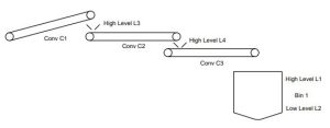
- When this counter counts to preset, the number of boxes on Conveyor 2 has counted to 4 and the boxes are now ready to be moved as a group to a third conveyor.
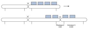
To count the boxes off Conveyor 2 requires using a second counter or a down counter with the same address as the up-counter for counting boxes onto conveyor 2. Write the code that moves the boxes off the conveyor.
- The microwave is to be set for high for 1:30 (one minute, thirty seconds) to cook my oatmeal. The oatmeal sometimes boils and bubbles out of the bowl if left on continuously for 1:30 but the time is to be held at 1:30. Design a control circuit to guarantee 1:30 cooking time with no over-flow mess. Use sensors as needed and a start button and ready light to complete the control scheme. Design a function/state – signal assignment table to accompany your program. This is a retentive timer application. Use a retentive timer from either A-B or Siemens.
- Design a de-bounce circuit which will override the bounce of a limit switch on the
leading edge only. Allow no input that is not on for at least .5 second. Use Limit_switch_1 as input. - Siemens and A-B have different contact descriptors for the same functions. In the following, the A-B contacts are listed. Fill in the Siemens’ equivalent:
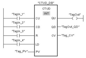
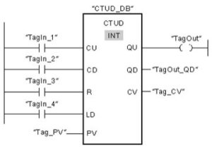
- Convert the following Siemens Counter to its A-B equivalent:
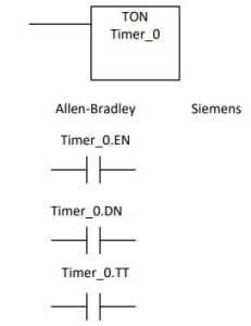
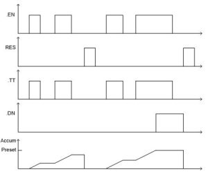
- The following timing diagrams represent a type of timer. Show an example from Siemens and Allen-Bradley to demonstrate the timer. Identify in the example each variable and where it is found in the program:
- Using non-counter PLC instructions, write logic to perform the function of the counter below:
- A car wash with two bays has a pump supplying water pressure to the spray heads. If a bay in use contact turns on, one pump automatically turns on. If a water pressure switch is not satisfied (sufficient pressure) and a delay of 5 seconds occurs, a second pump turns on. If, after the second pump turns on and water pressure is not satisfied and a 10 second delay occurs, a third pump is turned on. All pumps stay on for the duration of the wash and turn off after both bay in use contacts turn off.
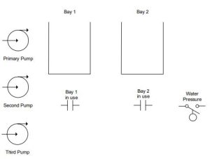 Write Ladder Logic to Turn on the Outputs using Ladder Logic for the Problem above: What could you do to enhance the logic for this process?
 - Change the problem above per:A car wash with two bays has a pump supplying water pressure to the spray heads. If a bay in use contact turns on, one pump automatically turns on. If a water pressure switch is not satisfied (sufficient pressure) and a delay of 5 seconds occurs, a second pump turns on. If, after the second pump turns on and water pressure is not satisfied and a 10 second delay occurs, a thirdpump is turned on. Pumps remain on until one of the bay in use contacts turns off at which time pump 2 and 3 turn off and the timer circuits again may turn on additional pumps if the pressure is not satisfied. If both contacts turn off, all pumps turn off.
- 1Also, the following:
A car wash with two bays has two pumps supplying water pressure to the spray heads. If a bay in use contact turns on, one pump automatically turns on. If a water pressure switch is not satisfied (sufficient pressure) and a delay of 30 seconds occurs, a second pump turns on. Pump 2 remains on until one of the bay in use contacts turns off at which time pump 2 turns off and the timer circuit again may turn on pump 2 if the pressure is not satisfied. If both contacts turn off, all pumps turn off.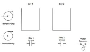
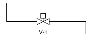
- The following valve has two limit switches, one that energizes when the valve is closed and one that is energized when the valve is full open. Write a ladder logic program that turns on an alarm if the time turn from on to off or off to on exceeds 5 seconds. The alarm should stay on until a reset button is energized.
- A button can turn on a motor only once every 20 minutes. Write a ladder logic program that prevents the motor from being turned on more often.
Lab 7.1 The Traffic Intersection
A traffic intersection has the following three lane assignments: East-West Thru
North-South Turn North-South Thru
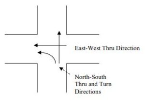
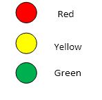
Two sets of traffic lights are found for each turn direction although the lab uses only one set. Each turn direction has a set of three lights as follows:
Although traffic intersection logic tends to be very complicated in order to provide fool-proof operation of the traffic intersection, a simplified chart of the operation of the lights can be used to program the lights and operate the intersection. Each interval is an interval of time and after the last interval, the process repeats from the top. The intersection’s operational chart:
This lab consists of programming the nine lights to cycle through the proper sequence to control traffic flow at the intersection described above.
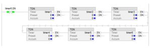
A helps program can be found accompanying this lab to start the process of setting up timers, especially to cycle and repeat a sequence. Notice that two timers can be set up the same as six or more timers to control such events as a flashing yellow or flashing red light. The same two timers can be used for all such flashing functions. Thus, two timers are all that are needed if a flashing sequence is needed.
Notice the EN, DN and TT contacts found with every timer. Timers start with T4:0 and proceed upward. Use the TON timer, or the On Delay Timer. Addressing for timer contacts is T4:0/DN, T4:0/TT, T4:0/EN. Refer to the Allen-Bradley Instruction Reference Manual for more detailed information about the use of timers. Also, look at the helps program to view a basic cycling program that works.
Also, the outputs must be programmed. Remember that only one output should be programmed for each light. Outputs are programmed to allow multiple branches to turn on the selected output. For instance, the top or bottom branch of the rung would allow the output to turn on.
This is a parallel branching function so either of these branches would turn on the output.
Options for Lab 7.1
- Lab 7.1 A Add a selector switch to delete intervals 3 and 4 during a rush hour.
- Lab 7.1 B Add a selector switch to blink N-S lanes yellow, E-W lanes red for late-night.
- Lab 7.1 C Add a short time delay between intervals 2-3, 4-5, and 6-1 while all lights are red.
- Lab 7.1 D Add a push button to allow pedestrians to walk in all directions for an interval of time while all lanes are red.
- Lab 7.1E Add a push button that acts as a button in the pavement that will only allow a turn lane signal if there has been a car activate the turn signal in the time prior to the turn signal’s position in the cycle.
- Lab 7.1F Add a switch imbedded in the road to sense when there is a back-up of cars wanting to use the turn lane. If there is a back-up, use a longer time preset for the turn lane. If the switch turns on rapidly, then there is no back-up. If the switch turns on but not in rapid succession, there is a back-up.
Hints for Lab 7.1
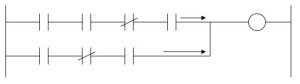
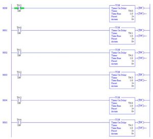
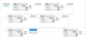
Program the timer circuit below to give the intervals needed. View the T4 Timer Table on-line with the processor running. Notice the TT and DN contacts. Use the TT (or EN or DN) contacts in logic to turn on the lights in order.

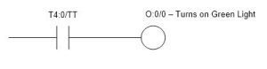
The logic to provide outputs and the outputs themselves may be combined. For instance, to turn on a specific traffic light from the program above, program the following:
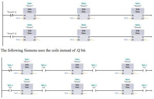
The following Siemens program will provide the same function as the A-B program above: You may use either the .Q bit or define timer output coils at each time interval.
You can try the following but it will not work properly. Do you know why?
The above A-B rung gives what result? Why?
Instead, use the following. Why will this work and not the above?
Using the Force Table
With inputs, to verify a working input was relatively easy. Simply wire through the button to the input terminal. If the input is working, the LED on the input block lights when the pushbutton is energized. With outputs, life is not as simple. Both the wiring must be correct and the program work as well for the lights to function properly. To divide the task into two parts, RSLogix 500 provides a force function to overwrite the program and force the output bits on. The Force Table may be accessed through the System Tree.
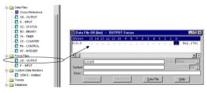
Force on outputs as necessary to turn on lights. When done checking lights, do not forget to delete all forces.
Lab 7.2 The Cash Register
Design a simple cash register similar to one found at McDonald’s or Burger King. To do this, determine a menu of five or six items from the restaurant. Also, include a Total button or a clear button or possibly both. Also, include a means for backing out of a mistake without starting over from zero. Display the cost of the total order in the PLC at an address in the data table. Use Floating Point Math with two decimal places.
For example
Find the approximate prices from a McDonald’s or Burger King for the items you choose. When an item is entered, its count is incremented automatically by one. If a button is entered multiple times, the count is incremented to display the total count. If a mistake is made, the attendant must be able to back up at least one entry and erase the last item or decrement that item by one.
- Display the final total in the PLC (not on the display of the trainer). Options to the lab:
- Lab 7.2 A Add logic for “To Go” order so that 6.25% tax is added if not “To Go”.
- Lab 7.2 B Add lights to buttons so that when an entry is made, the light lights.
- Lab 7.2 C Add logic to keep track of total number of each entry for the day.
- Lab 7.2 D Calculate profit for the day using your own profit numbers for each entry.
- Lab 7.2 E Automatically recognize that the entry of the individual items such as Whopper, Fries, and Drink will be given the price of the Whopper Combo instead of the individual prices.
Hints to the base lab
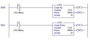
Notice that counters may be referenced as either Count Up or Count Down. If the count is counting up, the count is incremented in rung 0000. If the count is counted down, the count is decremented in rung 0001. Individual inputs are used to increment each product choice.
However, to decrement the count, a separate button labeled “Cancel Last” is used. This button must remember the last product chosen and decrement that item. Use the logic in chapter 6 “Relay Instructions” to remember when a button was pushed.
The circuit above is for trial purposes only. Do not use it “as is” in the logic of programs.
The amount of each product is held in the counter Acc value. To access these values, use the addressing of C5:0.ACC (or C5.0.2).
Values of each product are multiplied by the amount of the item and the final total is summed together.
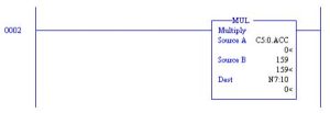
The number in Source B may be either a constant (as is here), or a value from a N7 location. If from an N7 location, the value that is to be used must be entered into that N7 location.
You may use the Siemens’ HMI instead of the wired buttons. More information about configuring the HMI may be found at:
Siemens SIMATIC S7-1200 Part 3 – Adding an HMI to a controller project: See how easy it is to integrate HMI screens into the controller user program using the same Step 7 Basic Software for both SIMATIC Basic HMI panels and S7-1200 Controllers. This is part three of a four part series.
A Simple HMI Tutorial (Siemens)
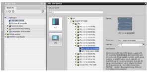
Again, the Siemens processor is to be configured similar to before:
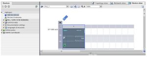
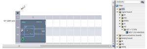
Before and after addition of the signal board:
Addition of the HMI used in the labs:
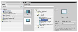
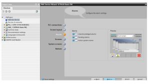
The HMI Device Wizard:
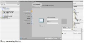
Keep answering Next>>
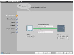
Keep answering Next>>
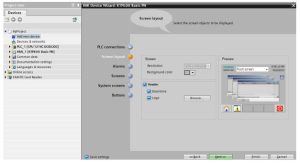
Keep answering Next>>
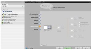
Then Finish
From the Devices and Networks choice in the Project Tree:
Choose Devices & networks

and set up both the IP address and Subnet mask for the PLC as well as the HMI. You may need to initialize the IP address of the HMI by setting the IP address up at power-up of the device.
You have about 1 second to tap on the screen when power is first applied to get to the set-up screen. Set up the IP address of the HMI to 5 (192.168.0.5, 255.255.255.0). Read at the end of Ch. 15 about setting up a simulated HMI panel simulated on the computer screen.
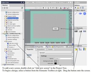
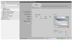
Entering a Button on the Screen and configuring the button to turn on a bit in the PLC Button The Button object allows you to configure an object that the operator can use in runtime to execute any configurable function.
Button Layout
In the Inspector window, you customize the position, geometry, style, color and font types of the object. You can adapt the following properties in particular:
● Mode: Defines the graphic representation of the object.
● Text / Graphic: Defines whether the Graphic view is static or dynamic.
● Define hotkey: Defines a key, or shortcut that the operator can use to actuate the button.
You can only define a hotkey for HMI devices with keys.
Mode for Button
The button display is defined in Properties > Properties > General >Mode in the Inspector window. Mode Description
Invisible The button is not visible in runtime.
Text The button is displayed with text. This text explains the function of the button.
Graphic The button is displayed with a graphic. This graphics represents the function of the button.
Depending on the device, Text /Graphic is also available.
The Mode property settings are used to define whether the display is static or dynamic. The display is defined in Properties > Properties > General >Text or Graphic in the Inspector window. Your options for the type Graphic include the following.
To turn on the bit in the PLC, use Press:
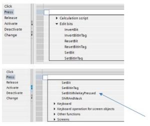
and then SetBitWhileKeyPressed:
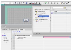
The tag is built in the PLC for an internal bit and referenced to the SetBitWhileKeyPressed
function:
There are a number of input types for data entry from the HMI. They include:
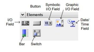
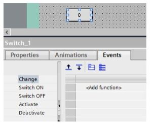
For Switch, the following choices are available:
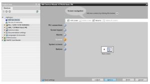
Screen Navigation
You will also need to consider configuring screen navigation. For a production process consisting of multiple sub-processes, you will configure multiple screens. You have the following options to enable the operator to switch from one screen to the next in Runtime:
- Assign buttons to screen changes
- Configuring screen changes at local function keys
Procedure
The procedure for configuring screens follows:
Before you create a screen change, define the plant structure and derive from it the screen changes that you want to configure.
Create the start screen under Runtime Settings > General > Start screen.
You will need to assign a button to change the screen. You will need to configure a button in the screen to switch between the screens on the HMI device during operation.
Procedure
- Double-click Screen_1 in the project navigation.
- Move Screen_2 from the project tree to the open screen by drag&drop. A button with the name Screen_1 is inserted.
- In the Inspector window, select Properties > Events > Click. The ActivateScreen system function is displayed in the “Function list”.
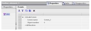
4. At the Object number attribute, define, if required, the tab sequence number of the object on which the focus is to be set after a screen change. You can also specify a tag that contains the object number.
Overview of HMI tag tables
HMI tag tables contain the definitions of the HMI tags that apply across all devices. A tag table is created automatically for each HMI device created in the project. In the project tree there is an HMI tags folder for each HMI device. The following tables can be contained in this folder:
- Standard tag table
- User-defined tag tables
- All tags
The following tables are also available in an HMI tag table:
- Discrete alarms
- Analog alarms
With the help of these tables you configure alarms for the currently selected HMI tag.
In the project tree you can create additional tag tables in the HMI tags folder and use these to sort and group tags and constants. You can move tags to a different tag table using a drag&drop operation or with the help of the Tag table field. You activate the Tag table field using the shortcut menu of the column headings.
Standard tag table
There is one standard tag table for each HMI device of the project. It cannot be deleted, renamed or moved. The standard tag table contains HMI tags and, depending on the HMI device, also system tags. You can declare all HMI tags in the standard tag table, or create additional user- defined tag tables as you want.
User-defined tag tables
You can create multiple user-defined tag tables for each HMI device in order to group tags according to your requirements. You can rename, gather into groups, or delete user-defined tag tables. To group tag tables, create additional subfolders in the HMI tags folder.
All tags
The All tags table shows an overview of all HMI tags and system tags of the HMI device in question. This table cannot be deleted, renamed or moved.
Discrete alarms table
In the Discrete alarms table, you configure discrete alarms to the HMI tag selected in the
HMI tag table. When you configure a discrete alarm, multiple selections in the HMI tag table is not possible. You configure the discrete alarms for each HMI tag separately.
Analog alarms table
In the Analog alarms table, you configure analog alarms to the HMI tag selected in the HMI tag table. When you configure an analog alarm, multiple selections in the HMI tag table is not possible. You configure the analog alarms for each HMI tag separately.
Defining Limits for a Tag
For numerical tags, you can specify a value range by defining a low and high limit. Additionally, you configure the system to process a function list whenever a tag value drops below or exceeds its configured value range.
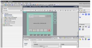
You may want to simulate the HMI screen instead of downloading to an actual screen. In this case, the blue button at the top of the screen allows this action. It saves a great deal of time setting up a separate HMI and you should not need the actual screen until using in the real world.
If you do not see numbers from the PLC appearing in the HMI screen or Inputs not working from the HMI to the PLC, refer to the instructions at the end of Ch. 15 of this text for a set-up procedure that must be followed to ensure that communication takes place.
Instead of creating the same explanation for A-B, refer to the following Getting Results Guide. It will get you up to speed on how to create an HMI screen or screes for the A-B PLC program.