
Chapter 8 Exercises & Labs
Exercises
- Write a rung to turn on a coil when the value in int_1 > 20 and int_2 < 25.
- Write a rung to turn on a coil when the value in int_1 < 20 or float_1 > 8.
- Write a rung to turn on a coil when the value in byte_3 < 120.
- Multiply 10 * int_1 and display results in an integer variable.
- Divide the contents of int_4/(constant = 4).
- Write logic to create six time intervals as in the traffic light problem but using only one timer: (Only provide enough code to illustrate the concept.)
- Two numbers are stored in float_1 and float_2. If these numbers represent the sides of a triangle, find the length of the hypotenuse.
- Write a single rung to turn on an output when the value in int_1 is less than 200, greater than 1000 or equal to 555:
- The accumulated number of widgets on the production line is found in counter widget_count_accum. Each widget is worth 35 cents. Write ladder logic to show in total_cost the total worth of widgets on the line. What are the numerical limitations of your calculation?
- Write a rung of logic that turns on when the number in int_1= 22. Use only relay contacts and one output coil.
- Three numbers are stored in int_1, int_2 and int_3. Find the average of these three numbers and store the results.
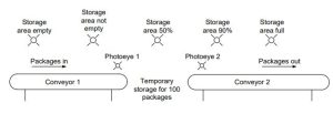
- The following conveyor system has five outputs, lights for percent complete of packages going down conveyor 1 to conveyor 2. Write a program to turn on these lights based on the fact that packages must pass photoeye 1 to enter the storage area and pass photoeye 2 to exit.
- Use Fig. 8-25 and describe how to program high and low limit tests with Siemens and CompactLogix Ladder Logic.
- Use Fig. 8-27 and describe how to program a dead band application with Siemens and CompactLogix Ladder Logic.
- Find the equivalent instruction to the SCP instruction for the Siemens and CompactLogix processors.
- Describe a program statement to add 1% to the full scale value of a variable using the Siemens and CompactLogix processors.
- Write the loss-in-weight portion of the paper-making process in which weight is lost from a scale that feeds pulp to the batch. The scale is represented by a number that must decrease a set amount from an arbitrary number downward a set amount. During the feed cycle, an output is on running a loss-in-weight feeder, usually a vibratory feed device.
- Finish the Juice Condensate program using numbers for states.
- Convert the following seal circuit to a S/R circuit.

- Write logic to place the material in the festooner box:
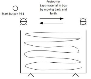
- The festooner pictured above now lays material in a box by moving an arm back and forth. The action reverses after a small time delay after hitting the end-of-travel photo-eye. The box is considered complete when the weight exceeds 100 pounds or 50 back-and-forth actions – whichever occurs first. Design an I/O table and write a program in Ladder Logic to perform the action.
- The festooner pictured above is changed to lay material into the box with an arm that moves left and right with the following conditions:
The sensors at each end stop the movement and, after a short time delay, reverse the motion. The scale under the box records the weight at the beginning of the fill. The arm stops close to when 100# is met. The arm is to come to rest at the left sensor. If the weight isn’t yet at 100# but closer to 100# than if the arm were to move through another pass, the arm is to stop and the operation is over. The goal is to place as close to 100# material as possible with the fill ending at the left sensor. - Write a program that turns on a heater when the temperature falls less than 300 oF and turns off the heater when the temperature exceeds 325 oF for the liquid in a vessel. The temperature is input in a variable labelled ‘temp’. In a table, define each variable used by type.
- Design a ramp up block for the lab below using the servo motor (Ramp to setpoint).
Lab 8.1 Integer Math
- Lab 8.1a: Using only contacts and coils, add two integer numbers found in two integer numbers. Counts may be 8 bit, 16 bit or 32 bit in length.
- Lab 8.1b: Using only contacts and coils, subtract one integer number from another integer.
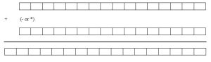
- Lab 8.1c: Using only contacts and coils, multiply two integer numbers. Use the following as a guide to labs 8.1:
- Lab 8.1d:Using only contacts and coils, create an equivalent of an up counter. Use inputs for counting up and count reset. Turn on an output when the count equals a preset. For memory, use latch or coil outputs. Make the counter 8 bits long or from 0 to 255. Use a constant in an integer location for the compare (between 0 and 255).
- Lab 8.1e: Using only contacts and coils, create an equivalent of a down counter. Use inputs for counting down and count reset. Turn on an output when the count equals a preset. For memory, use latch or coil outputs. Make the counter 8 bits long or from 0 to 255. Use a constant in an integer location for the compare (between 0 and 255).
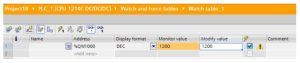
Watch Tables and Force Tables[1]
You use “watch tables” for monitoring and modifying the values of a user program being executed by the online CPU. You can create and save different watch tables in your project to support a variety of test environments. This allows you to reproduce tests during commissioning or for service and maintenance purposes.
With a watch table, you can monitor and interact with the CPU as it executes the user program. You can display or change values not only for the tags of the code blocks and data blocks, but also for the memory areas of the CPU, including the inputs and outputs (I and Q), peripheral inputs (I:P), bit memory (M), and data blocks (DB).
With the watch table, you can enable the physical outputs (Q:P) of a CPU in STOP mode. For example, you can assign specific values to the outputs when testing the wiring for the CPU.
STEP 7 also provides a force table for “forcing” a tag to a specific value. For more information about forcing, see the section on forcing values in the CPU in the “Online and Diagnostics” chapter.
Note: The force values are stored in the CPU and not in the watch table.
You cannot force an input (or “I” address). However, you can force a peripheral input. To force a peripheral input, append a “:P” to the address (for example: “On:P”).
Cross reference to show usage[2]
The Inspector window displays cross-reference information about how a selected object is used throughout the complete project, such as the user program, the CPU and any HMI devices. The “Cross-reference” tab displays the instances where a selected object is being used and the other objects using it. The Inspector window also includes blocks which are only available online in the cross-references. To display the cross-references, select the “Show cross-references” command. (In the Project view, find the cross references in the “Tools” menu.)
Note: You do not have to close the editor to see the cross-reference information.
You can sort the entries in the cross-reference. The cross-reference list provides an overview of the use of memory addresses and tags within the user program.
Lab 8.2 PWM and RAMP
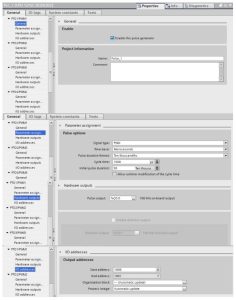
In this lab we are introduced to the PWM output of the Siemens 1200 PLC. Described below is the configuration of the PWM output channels of the first 4 outputs of the Siemens S7-1215 DCDCDC processor. The configuration shown is just part of the process to program a pwm output.
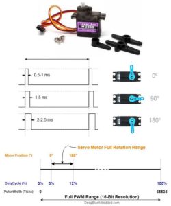
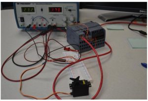
The picture below is a hobby servo controller. The movement and control is based on a number in the output word associated with the output. With a configuration as above, the pulse width is determined by the servo specification. The specification below shows 1500 micro seconds or 1.5 msec duration. Both servo applications below use the HS-422 servo motor.

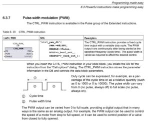
The instruction for driving the PWM output is the CTRL_PWM instruction. This instruction is explained in the Easy Manual and copied below: “
Lab 8.2A
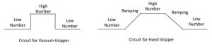
This lab requires the number in QW1000 to be modulated between two numbers to engage the vacuum and disengage the vacuum. The numbers and command to turn the vacuum on and off must be determined by trial and error.


Lab 8.2B
This lab requires the number in QW1000 to be modulated between two numbers to open and close the gripper. The numbers and command to open and close must be determined by trial and error. There must be a ramping of the numbers between the open and close values in order to move the gripper gradually instead of in a jerking manner. The speed of the move should be a variable controlled by the program.

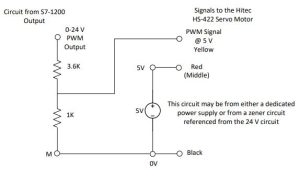
The time to close and time to open should be programmable and controlled. The speed at which these grippers close should be a variable in the program. The signal is wired as shown below.

From the Hitec Manual:
Pulse Data
All Hitec servos require 3-5V peak to peak square wave pulse. Pulse duration is from 0.9mS to 2.1mS with 1.5mS as center. The pulse refreshes at 50Hz (20mS).
Voltage Range
All Hitec Servos can be operated within a 4.8V-6V. range.
Only the HS-50 operates exclusively with 4 Nicad cells ( 4.8 volt ).
Wire Color Meanings
On all Hitec servos the Black wire is ‘ground’, the Red wire ( center ) is ‘power’ and the third wire is ‘signal’.
Direction of Rotation
All Hitec servos turn Clockwise direction ( CW )
The circuit below shows the electrical connection and design to be used in the program for controlling the two grippers:
The following figures outline the method of setting up the PWM output for the PLC and servo. The next figure shows the PWM instruction which must be added to the program. It may be inserted in any OB that is active. This instruction is inserted in OB1.
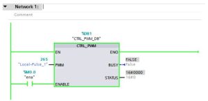
The configuration of the PWM for output on output 0.0 for the above servo is as follows:
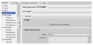
This must be done before the program is loaded and run. It should also be saved before running.
The following sets up the pulse duration for the servo above that requires a pulse duration of 20 msec.
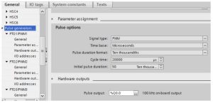
The following sets up the output word for entry of the pulse length in QW1000 (includes 1001):
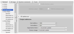
The above initialization allows the user (program) to input values in the QW1000 location to test the servo using the Watch Table:
The experiment concludes with the values for the limits of QW1000 found. Completely clockwise is 175 and completely counter-clockwise is 1275. The servo ranges from 0 to 180o in the process. The power supply shown is a good way to provide the +5V and +24 V to the process. This power supply has a variable supply A and B that can be set to close to +24 V.
The experiment does not end here. This lab continues with a program in Lab Text Ch. 8. The inclusion of four servo controllers in Ch. 13 in the discussion of arrays and Lab Text Ch. 31 where the program for moving of the robot built with the four servo controllers is discussed.
