
8 Math Functions *
Introduction
The introduction of mathematical operations in the PLC provided major benefits to control logic. Numeric data could be combined with logic to provide more powerful control strategies. For instance, decisions could be made concerning mathematical operations concerning counts of products, weights of a product, the temperature of an oven or any numeric variable in a process.
Siemens Math Instructions
The instructions are briefly divided into three categories: Compare Blocks, Math Blocks and Move Blocks. First will be the Compare blocks:
Again, instructions given have the TIA definition quoted below. The full definition for these instructions can be found in the reference manual.
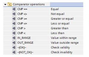
Compare Instruction

“You use the compare instructions to compare two values of the same data type. When the LAD contact comparison is TRUE, then the contact is activated. When the FBD box comparison is TRUE, then the box output is TRUE.
Relation type The comparison is true if:
== IN1 is equal to IN2
<> IN1 is not equal to IN2
>= IN1 is greater than or equal to IN2
<= IN1 is less than or equal to IN2 > IN1 is greater than IN2
< IN1 is less than IN2”
In Range and Out of Range Instructions
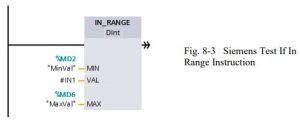
“You use the IN_RANGE and OUT_RANGE instructions to test whether an input value is in or out of a specified value range. If the comparison is TRUE, then the box output is TRUE.
The input parameters MIN, VAL, and MAX must be the same data type.”
Relation type The comparision is TRUE if:
IN_RANGE MIN <= VAL <= MAX OUT_RANGE VAL < MIN or VAL > MAX
OK and Not OK Instructions
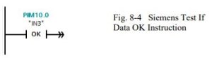
“You use the OK and NOT_OK instructions to test whether an input data reference is a valid real number according to IEEE specification 754. When the LAD contact is TRUE, the contact is activated and passes power flow. When the FBD box is TRUE, then the box output is TRUE.”
Instruction The Real number test is TRUE if:
OK The input value is a valid Real number NOT_OK The input value is not a valid Real number
Math Instructions
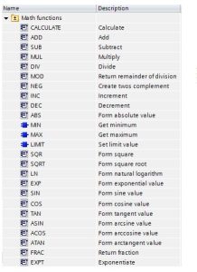
Add, Sub, Mul, Div, Calculate
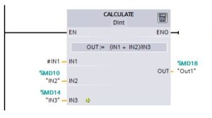
“You use a math box instruction to program the basic mathematical operations:
- ADD: Addition (IN1 + IN2 = OUT)
- SUB: Subtraction (IN1 – IN2 = OUT)
- MUL: Multiplication (IN1 * IN2 = OUT)
- DIV: Division (IN1 / IN2 = OUT)
An Integer division operation truncates the fractional part of the quotient to produce an integer output.
When enabled (EN = 1), the math instruction performs the specified operation on the input values (IN1 and IN2) and stores the result in the memory address specified by the output parameter (OUT). After the successful completion of the operation, the instruction sets ENO = 1.”
ENO status Description
1 No error
0 The Math operation result value would be outside the valid number range of the data type selected. The least significant part of the result that fits in the destination size is returned.
0 Division by 0 (IN2 = 0): The result is undefined and zero is returned.
0 Real/LReal: If one of the input values is NaN (not a number) then NaN is returned.
0 ADD Real/LReal: If both IN values are INF with different signs, this is an illegal operation and NaN is returned.
0 SUB Real/LReal: If both IN values are INF with the same sign, this is an illegal operation and NaN is returned.
0 MUL Real/LReal: If one IN value is zero and the other is INF, this is an illegal operation and NaN is returned.
0 DIV Real/LReal: If both IN values are zero or INF, this is an illegal operation and NaN is returned.
Mod
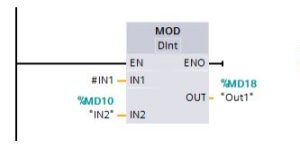
“You use a MOD (modulo) instruction for the IN1 modulo IN2 math operation. The operation IN1 MOD IN2 = IN1 – (IN1 / IN2) = parameter OUT.”
NEG
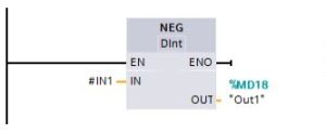
“You use the NEG (negation) instruction to invert the arithmetic sign of the value at parameter IN
and store the result in parameter OUT.”
Increment and Decrement
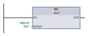
“You use the INC and DEC instructions to:
Increment a signed or unsigned integer number value
INC (increment): Parameter IN/OUT value +1 = parameter IN/OUT value
Decrement a signed or unsigned integer number value
DEC (decrement): Parameter IN/OUT value – 1 = parameter IN/OUT value”
Absolute Value
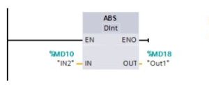
“You use the ABS instruction to get the absolute value of a signed integer or real number at parameter IN and store the result in parameter OUT.”
MIN and MAX
“You use the MIN (minimum) and MAX (maximum) instructions as follows:
MIN compares the value of two parameters IN1 and IN2 and assigns the minimum (lesser) value to parameter OUT.
MAX compares the value of two parameters IN1 and IN2 and assigns the maximum (greater) value to parameter OUT.”
Limit
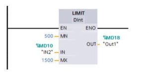
“You use the Limit instruction to test if the value of parameter IN is inside the value range specified by parameters MIN and MAX. The OUT value is clamped at the MIN or MAX value, if the IN value is outside this range.
If the value of parameter IN is inside specified range, then the value of IN is stored in parameter OUT.
If the value of parameter IN is outside of the specified range, then the OUT value is the value of parameter MIN (if the IN value is less than the MIN value) or the value of parameter MAX (if the IN value is greater than the MAX value).”
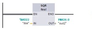
Floating-Point Math
You use the floating point instructions to program mathematical operations using a Real or LReal data type:
- SQR: Square (IN 2 = OUT)
- SQRT: Square root (√IN = OUT)
- LN: Natural logarithm (LN(IN) = OUT)
- EXP: Natural exponential (e IN =OUT), where base e = 2.71828182845904523536
- SIN: Sine (sin(IN radians) = OUT)
- COS: Cosine (cos(IN radians) = OUT)
- TAN: Tangent (tan(IN radians) = OUT)
- ASIN: Inverse sine (arcsine(IN) = OUT radians), where the sin(OUT radians) = IN
- ACOS: Inverse cosine (arccos(IN) = OUT radians), where the cos(OUT radians) = IN
- ATAN: Inverse tangent (arctan(IN) = OUT radians), where the tan(OUT radians) = IN
- FRAC: Fraction (fractional part of floating point number IN = OUT)
- EXPT: General exponential (IN1 IN2 = OUT)
MOVE Operations
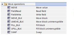
“Use the move instructions to copy data elements to a new memory address and convert from one data type to another. The source data is not changed by the move process.
MOVE: Copies a data element stored at a specified address to a new address MOVE_BLK: Interruptible move that copies a block of data elements to a new address UMOVE_BLK: Uninterruptible move that copies a block of data elements to a new
Address”
MOVE_BLK, UMOVE_BLK
“The MOVE instruction copies a single data element from the source address specified by the IN parameter to the destination address specified by the OUT parameter. The MOVE_BLK and UMOVE_BLK instructions have an additional COUNT parameter. The COUNT specifies how many data elements are copied. The number of bytes per element copied depends on the data type assigned to the IN and OUT parameter tag names in the PLC tag table.”
Fill
“You use the FILL_BLK and UFILL_BLK instructions as follows:
FILL_BLK: The interruptible fill instruction fills an address range with copies of a specified data element.
UFILL_BLK: The uninterruptible fill instruction fills an address range with copies of a specified data element.”
Swap
“You use the SWAP instruction to reverse the byte order for two-byte and four-byte data elements. No change is made to the bit order within each byte. ENO is always TRUE following execution of the SWAP instruction.”
Convert
“You use the CONVERT instruction to convert a data element from one data type to another data type. Click below the box name and then select IN and OUT data types from the dropdown list. After you select the (convert from) data type, a list of possible conversions is shown in the (convert to) dropdown list. Conversions from and to BCD16 are restricted to the Int data type. Conversions from and to BCD32 are restricted to the DInt data type.”
Round and Truncate
“ROUND converts a real number to an integer. The real number fraction is rounded to the nearest integer value (IEEE – round to nearest). If the Real number is exactly one-half the span between two integers (i.e. 10.5), then the Real number is rounded to the even integer. For example, ROUND (10.5) = 10 or ROUND (11.5) = 12.”
Ceiling and Floor
“CEIL converts a real number to the smallest integer greater than or equal to that real number (IEEE – round to +infinity).
FLOOR converts a real number to the greatest integer smaller than or equal to that real number (IEEE – round to -infinity).”
Scale and Normalize
“SCALE_X scales the normalized real parameter VALUE where ( 0.0 <= VALUE <= 1.0 ) in the data type and value range specified by the MIN and MAX parameters:
OUT = VALUE ( MAX – MIN ) + MIN”
Allen-Bradley SLC Math Instructions
A Review of Math Function Blocks from SLC-500 Reference Manual:
| ADD | Add | Adds source A to source B and stores the result in the destination |
| SUB | Subtract | Subtracts source B from source A and stores the result in the destination |
| MUL | Multiply | Multiplies source A by source B and stores the result in the destination |
| DIV | Divide | Divides source A by source B and stores the result in the destination and the math register |
| DDV | Double Divide | Divides the contents of the math register by the source and stores the result in the destination and the math register |
| CLR | Clear | Sets all bits of a word to zero |
| SQR | Square Root | Calculates the square root of the source and places the integer result in the destination |
| SCP | Scale with Parameters | Produces a scaled output value that has a linear relationship between the input and scaled values |
| SCL | Scale Data | Multiplies the source by a specified rate, adds to an offset value, and stores the result in the destination |
| ABS | Absolute | Calculates the absolute value of the source and places the result in the destination |
| CPT | Compute | Evaluates an expression and stores the result in the destination |
| SWP | Swap | Swaps the low and high bytes of a specified number of words in a bit, integer, ASCII, or string file |
| ASN | Arc Sine | Takes the arc sine of a number and stores the result (in radians) in the destination |
| ACS | Arc Cosine | Takes the arc cosine of a number and stores the result ( in radians) in the destination |
| ATN | Arc Tangent | Takes the arc tangent of a number and stores the result (in radians) in the destination |
| COS | Cosine | Takes the cosine of a number and stores the result in the destination |
| LN | Natural Log | Takes the natural log of the value in the source and stores it in the destination |
| LOG | Log to the Base 10 | Takes the log base 10 of the value in the source and stores the result in the destination |
| SIN | Sine | Takes the sine of a number and stores the result in the destination |
| TAN | Tangent | Takes the tangent of a number and stores the result in the destination |
| XPY | X to the Power of Y | Raise a value to a power and stores the result in the destination” |
Some instructions are available for all processors. Some of the more advanced instructions are only available with the more powerful processors.
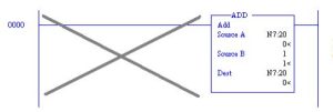
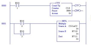
An example of a math block used in logic follows:
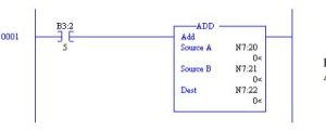
The ADD Block above adds the contents of N7:20 to the contents of N7:21 and saves the result in location N7:22. This occurs only when B3:2/5 is true.
Using one-shot logic with the ADD Block:
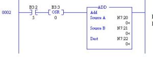
The ADD Block above adds the contents of N7:20 to the contents of N7:21 and saves the results in N7:22 only on the leading edge of B3:2/5. The use of the one-shot allows only a single occurrence of the calculation and is a very efficient way to execute math operations.
Use of the Continuous Execution Math Block:
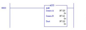
The ADD Block above adds the same data as earlier. In this example, however, execution of the
ADD Block occurs continuously (once each scan). Use of Constants in Math Blocks:
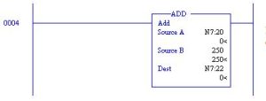
In this example, the ADD Block adds a variable (N7:20) to a constant (250) and places the results in a variable location (N7:21).
The decision must be made when programming how to treat constants. If the number in Source B above is never changed, then entering 250 into Source B is the preferred approach. If the number is to be changed at a later date, however, use the addressing approach below and store the number 250 in N7:21.
There is a dilemma with entering a constant in a storage location. This occurs if a second person changes the value in the N7 location at a later date. The documentation of the listing does not keep the constant’s value and the value of the constant 250 is lost unless it is kept in a rung comment (a very good reason to have rung comments). A compromise is reached with the addition of a rung to load the constant’s value to the variable location at power-up or with the restart of RUN mode. This approach employs use of the first scan bit, S:1/15.
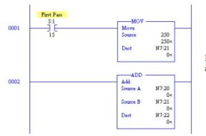
The above two rungs show an example of an ADD Block using a constant that may be changed but is restored each occurrence that power is restored or the processor is returned to the RUN mode.
Multiple Step Calculations
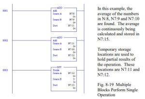
A calculation may require more than one block as shown below in Fig. 8-8. If the file N7 is used, the address refers to an integer. If the file F8 (not applicable to MicroLogix processors), the number refers to a floating point number. Mixing of integer and floating-point numbers in the operation may be used if floating point is allowed by the processor. Some of the instructions listed in Table 8-1 are not allowed on the MicroLogix processors.
Example of Use of Calculation Blocks:
Three numbers are stored in N7:8, N7:9 and N7:8. Find the average of these three numbers using PLC logic. Store the results in N7:15.
Compare Instructions
Another group of instructions use math expressions as contacts and are listed below. They form the group of Comparison Instructions:
Mnemonic Name Purpose
| EQU | Equal | Test whether two values are equal |
| NEQ | Not Equal | Test whether one value is not equal to a second value |
| LES | Less Than | Test whether one value is less than a second value |
| LEQ | Less Than or Equal | Test whether one value is less than or equal to a second value |
| GRT | Greater Than | Test whether one value is greater than another |
| GEQ | Greater Than or Equal | Test whether one value is greater than or equal to a second value |
| MEQ | Masked Comparison for Equal | Test portions of two values to see whether they are equal. Compares 16-bit data of a source address to 16-bit data at a reference address through a mask |
| LIM | Limit Test | Test whether one value is within the limit range of two other values” |
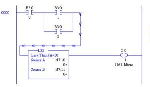
An example of the Compare Block is seen below:
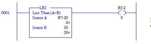
This rung turns on B3:2/0 as long as the number in N7:20 is less than 50. N7:20 ranges from – 32768 to +32767
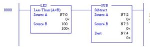
Math instructions are found at the output of a rung while comparison instructions are found as contacts that allow the output to operate under certain conditions. In the example, when the number in N7:0 is less than the number 100, the subtraction block will be performed. The subtraction block subtracts the number in N7:3 from the number in N7:2 and stores the result in N7:4.
Mixing of Relay Contacts and Compare Instruction:
The circuit above shows the combination of Comparison and contact logic turning on an output (O:0/1).
Multiple Compare Instructions:
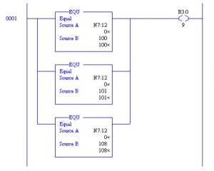
The circuit above gives a combination of Comparison statements that turn on output B3:0/9. If N7:12 is equal to any of the values 100, 101, or 108, the output turns on. This is an example of ‘OR’ logic. If N7:12 = 100 or N7:12 = 101 or N7:12 = 108, then turn on B3:0/9.
LIMIT Compare Block
The Limit Test (LIM) uses three values to determine if a value is within a certain limit. The three values are:
- Low Limit
- Test Value
- High Limit
If the test parameter is a constant, then both the low and high limit values must be word addresses. If the test parameter is a word address, then the low and high limit values may be either a constant or word address.
The LIM instruction passes power when the test value is between the two limits of the lower and upper limit. It is false when either above the high limit or below the lower limit. When the lower limit is greater than the upper limit, LIM true when the test value is greater than the lower number (stored in the upper limit) or less than the higher number (stored in the lower limit).
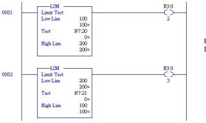
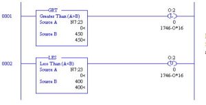
For example, in rung 0001 above, B3:0/2 will turn on if the value in N7:20 lies between 100 and
200. In rung 0002, B3:0/3 will turn on if the value in N7:21 is greater than 200 or is less than 100.
Other Compare Examples
To insert high and low limits on a number, use the following circuit:
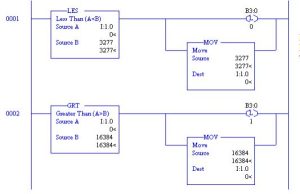
When the number input into I:1.0 ranges less than 3277 or higher than 16384, the number will be limited to the high value of 16384 or to the low value of 3277.
Comparison values to turn on a valve:
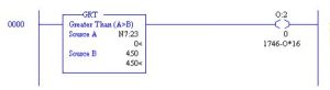
While the circuit above may be useful in turning on or off an output, usually a dead band must be inserted in the circuit so that output O:2/0 will not chatter on and off. Results of the circuit of are shown in the graph below. Note the chatter as the output turns on and off at a high frequency.
To slow the frequency to a much slower rate, the number in Source B must be made to vary and change so that the output must climb higher than 450 when increasing but turn off at a lesser value than 450 when falling.
For instance, if the output provided cooling to a process and the number 450 represents a temperature setpoint. N7:23 represents the value of the temperature of the process. If the temperature rises above 450 degrees, then turn on some cooling through output O:2/0. The circuit may work well as is, but if the output tends to chatter on and off, a dead-band circuit must be provided.
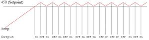
Output turns On-Off per Rung 0000.
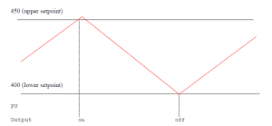
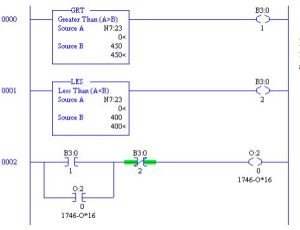
Fixing the High-Frequency On-Off with a Dead Band:
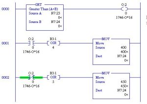
The circuit above provides a dead-band between 400 and 450 degrees. When the temperature rises above 450, the coolant solenoid turns on. When the temperature decreases to 400 degrees, the coolant turns off. Providing a dead-band keeps the coolant solenoid from constantly turning on and off. Care must be taken to initialize the circuit above to 450. One approach to this is with a rung triggered by S:1/15 (First Scan). One could also place 450 into N7:24 manually.
The second approach is not as trustworthy, however, since programs tend to be written over and constants lost with programs that change after the program has been working for days or even years.
Use of Memory using Latch or Seal with Compare
Combination of memory circuits with compare operations was subtly introduced in the example of the valve above. The two figures below provide functionally equivalent control of the dead- band problem with the temperature controller. However, the circuits employ standard memory logic to provide the same functional dead-band control.
This program uses latch-unlatch logic to turn on and off the output with a dead-band of 50 between the turn-on at 450 and turn-off at 400.
This program uses seal-circuit logic to turn on and off the output with a dead-band of 50 between the turn-on at 450 and turn-off at 400. Seal-circuit logic may be the preferred logic to use since it needs little additional logic to work correctly under all conditions.
Start-up conditions must be considered for each of the three approaches. With the first circuit, the initial status of N7:23 must be considered. Location N7:23 should be initialized to 450.
With the latch logic and the seal logic, the circuit will automatically initialize to a known value in all cases which is preferred. In general, using a seal circuit eliminates unnecessary logic to initialize the logic.
What is used as a memory component in the first of the three circuits above?
Status Table
When an arithmetic operation is performed, results from the operation are stored in the Status Table in a manner similar to the operation of a microprocessor. If two numbers are added, the carry and overflow are set or reset. Other operations use similar status bits. They are reviewed in the Table 8-3 below: (from Allen-Bradley’s SLC-500 Instruction Reference Manual)
| S:0/0 | Carry (C) | Sets if carry is generated; otherwise cleared |
| S:0/1 | Overflow (V) | Indicates that the actual result of a math instruction does not fit in the designated destination |
| S:0/2 | Zero (Z) | Indicates a 0 value after a math, move, or logical instruction |
| S:0/3 | Sign (S) | Indicates a negative (less than 0) value after a math, move, or logic instruction |
| S:5/0 | Minor Error Overflow | Set upon detection of a mathematical overflow or division by zero. If set upon execution of an END statement or a Temporary End (TND) instruction, or an I/O Refresh (REF), the recoverable major error code 0020 is declared.” |
Also, from the same manual, on Changes to the Math Register, S:13 and S:14, the status words for long integer math are described as follows:
“Status word S:13 contains the least significant word of the 32-bit values of the MUL and DDV instructions. It contains the remainder for DIV and DDV instructions. It also contains the first four BCD digits for the Convert from BCD (FRD) and Convert to BCD (TOD) instructions.
Status word S:14 contains the most significant word of the 32-bit values of the MUL and DDV instructions. It contains the unrounded quotient for DIV and DDV instructions. It also contains the most significant digit (digit 5) for the TOD and FRD instructions.”
Another table from the same reference book describes the math overflow or 32-bit integer math function. It is as follows:
Address Classification Description
| S:2/14 | Dynamic Config | Math Overflow Selection Bit Set this bit when you intend to use 32-bit addition and subtraction. When S:2/14 is set, and the result of an ADD, SUB, MUL, or DIV instruction cannot be represented in the destination address (underflow or overflow), – the overflow bit S:0/1 is set. – the overflow trap bit S:5/0 is set, and – the destination address contains the unsigned truncated least significant 16 bits of the result. The default condition of S:2/14 is reset (0). When S:2/14 is reset, and the result of an ADD, SUB, MUL, or DIV instruction cannot be represented in the destination address (underflow or overflow), – the overflow bit S:0/1 is set, – the overflow trap bit S:5/0 is set, and – the destination address contains 32767 if the result is positive or –32768 if the result is negative. Note: The status of bit S:2/14 has no effect on the DDV instruction. Also, it has no effect on the math register content when using MUL and DIV instructions. To program this feature, use the Data Monitor function to set or clear this bit. To provide protection from inadvertent data monitor alteration of your selection, program an unconditional OTL instruction at address S:2/14 to ensure the new math overflow operation. Program an unconditional OTU instruction at address S:2/14 to ensure the original math overflow operation.” |
This table shows a description of the operation to set S:2/14 when performing a 16 bit non- signed arithmetic operation instead of a 15 bit signed operation.
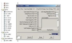
Status Table Math Section from RSLogix 500
Display of the Math portion of the Status Table can be seen by opening the Status Table file S2 and then the Math tab.
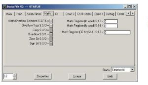
Notice the Math Register locations S:13 and S:14. The high order portion of the 32-bit number is saved in the ‘hi word’ and the low order portion is saved in the ‘lo word’.
A very good example of 32-bit addition is included in the Allen-Bradley SLC-500 Reference Manual. The introduction to the section on 32-bit math is important and should be reviewed prior to tackling this subject.
In general, math is done with the programmer choosing to use either integers or floating-point numbers. If possible, always use floating-point math. Integer math constantly must be concerned with overflowing the range of the number 32767 or –32768.
Using Advanced Math Instructions
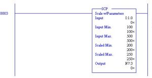
A very useful command found under the Advanced Math tab of RSLogix 500, is the SCP or Scale with Parameters block. The block above scales the input found at I:1.0 from an expected
input value ranging from 100 to 500 to an output value ranging from 200 to 250. This function allows for scaling of input and output values, multiplication of any number by a second number with an offset or any other mathematical operation of the form y = mx + b without performing the operation of the programmer mathematically calculating m or b.
Math Overflow Problem
Rungs should be examined before entered to insure that the rung will not allow a numeric overflow. The following is an example of a circuit that may experience an overflow:
In the figure above, after the processor is turned to the run mode, the ADD Block of rung 0000 is executed each scan rung 0000 is executed. Each scan the ADD Block is executed and 1 is added to N7:20. Since the result is stored in N7:20, this location is incremented by 1. Since a scan may take approximately 5 msec, in about 160 seconds, the number in N7:20 will reach 32767.
This instruction will fault the machine and the processor will turn off. The fault light will turn on.
Care must be taken to not program rungs such as rung 0000 above unless the contents of N7:20 are reset or limited in another rung. Use one-shots before math operations as a general rule to avoid situations such as the mistake above.
On the other hand, the use of a rung such as the one above may be useful in a program to calculate time duration of a scan. If properly used with a timer, the ADD Block may be programmed to calculate the average scan time of the program.
Status Table Contents on Faults
To clear a fault that stops the program from running and to diagnose the problem, click on S2 – STATUS in the Data Files section of the Project Tree. Then click Errors and read the description and analysis of the error in the window. An alternate method is simply reset the error from the Command Line and hope the fault doesn’t reoccur. It usually does. Make that, it always does.
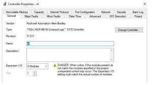
The CompactLogix Processor L16ER-BB1B gives the following properties page which is similar to the above SLC status page:
The RSLogix help topic “Access Runtime Controller Configuration and Status” describes the following:
S:FS First Scan flag
S:N Negative flag
S:Z Zero flag
S:V Overflow flag
S:C Carry flag
S:MINOR Minor Fault flag
Any other processor information must be obtained by using the GSV (get system variable) instruction.
When entering a GSV/SSV instruction, specify the object and its attribute to access. In some cases, there will be more than one instance of the same type of object. Be sure to specify the object name. For example, each task has its own TASK object that requires specifying the task name to gain access.
These are the GSV/SSV objects. The objects available for access are dependent on the controller.
- AddOnInstructionDefinition
- Axis
- Controller
- ControllerDevice
- CoordinateSystem
- CST
- DF1
- FaultLog
- HardwareStatus
- Message
- Module
- MotionGroup
- Program
- Redundancy
- Routine
- Safety
- SerialPort
- Task
- TimeSynchronize
- WallClockTime
Siemens gives similar results with the following pages when choosing the properties tab. We are not able to see every similar device for Siemens listed above. However, the help function for TIA provides a broad range of options for finding similar functions. We will discuss in Chapter 18 OB100, the Siemens start-up object block. This is the block containing instructions for start- up of the machine or re-initializing the machine after a shutdown.
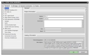
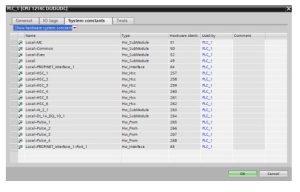
Fig. 8-34 Siemens Properties Pages
Use of Add Blocks
Use of Add blocks using the same Source and Destination addresses may be used. When programmed, a one-shot should be added to guarantee that the Add block does not continue for many scans. As an example, consider using a button to add 5% or 1% to a value in N7:29 in the range 1000 to 5000. The range of the ADD is 40 if 1% is chosen or 200 if 5% is chosen.
The circuit may be programmed as follows:
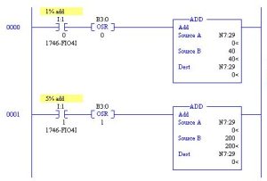
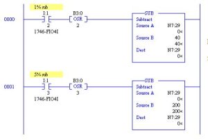
The two ADD Blocks above increment a number in N7:29 by either 1% or 5%. The following circuit decrements the number in N7:29 by 1% or 5%
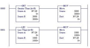
To protect the limits of 1000 or 5000 in N7:29, add the following:
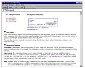
CPT Calculation Block
The CPT or Compute instruction is a very flexible instruction that is accessible only on SLC 5/03 through 5/05 processors. It provides expression statements similar to a computer language.
The CPT or Compute instruction is a very flexible instruction that is accessible only on SLC 5/03 through 5/05 processors. It provides expression statements similar to a computer language.
Multiple variables may be manipulated similarly to a statement in the language BASIC.
Mixing Counters and Math
With the math instructions available, it is now possible to combine circuits using relay contacts and coils, timers, counters and math operations. Coordination between the various rungs will continue to become more complicated as each new instruction is introduced.
Mixing of Data Types
Fig. 8-39 Example of Mixing Counting and Math
A very good feature of the PLC/5 and SLC architecture in general is the ability to mix numeric types in the same instruction. For instance, the instruction below adds the contents of F8:2 to N7:10 and places the results in B3:18. As can be seen, 0 + 0 = 0.
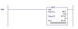
To mix numeric types, the difference between integer and floating point numbers must be taken into consideration. If an F location is added to an N location and the result is placed in an F location, the fraction will be kept. However, if the result is placed in an N location, the fraction will be lost. If this is desired, then mixed formatting is to be used.
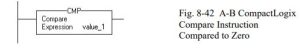
If you enter an expression without a comparison operator, such as value_1 + value_2, or value_1, the instruction evaluates the expression as follows:
If the expression is non-zero, tung-condition-out is set to true. If the expression is zero, the rung- condition-out is set to false. See the following:
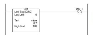
Limit Test (CIRC)
Example of Low Limit ≤ High Limit:
0 ≤ value ≥ 100, set light_1. If value < 0 or value > 100, turn off light_1.
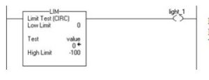
Example of Low Limit ≥ High Limit:
When value ≥ 0 or value < -100, set light_1. If value < 0 or value > -100, clear light_1.
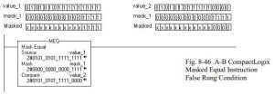
Mask Equal
Fig. 8-44 A-B CompactLogix Limit Instruction Testing for Value Outside the Range
The following example shows a true rung-condition-out for an MEQ command:

The following example shows rung-condition-out for an MEQ command that failed or was false:
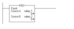
Equal
If value_1 is equal to value_2, set the rung-condition-out to true for the EQU command.
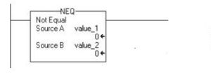
Not Equal
If value_1 is not equal to value_2, set the rung-condition-out to true for the EQU command.
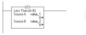
Less Than (A<B)
If value_1 is less than value_2, set the rung-condition-out to true for the LES command.
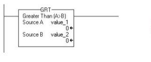
Greater Than (A>B)
If value_1 is greater than value_2, set the rung-condition-out to true for the GRT command.
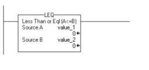
Less Than or Eql (A<=B)
If value_1 is less than or equal to value_2, then set the rung-condition-out to true for the LEQ
command.
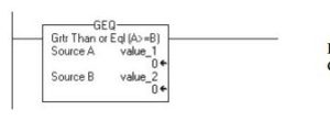
Grtr Than or Eql (A>=B)
If value_1 is greater than or equal to value_2, then set the rung-condition-out to true for the GEQ
command.
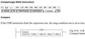
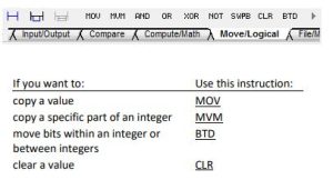
Compact Logix Compute/Math Instructions
![]()
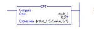
Compute
For the example, the CPT instruction, evaluates value_1 multiplied by 5 and divides the result by the result of value_2 divided by 7, placing the final result in result_1.
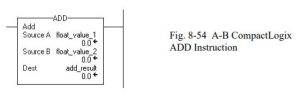
Add
The ADD instruction adds Source A to Source B and places the result in the Destination.
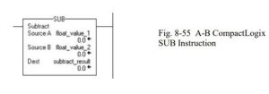
Subtract
Subtract float_value_2 from float_value_1 and place the result in subtract_result.
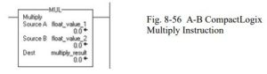
Multiply
Fig. 8-55 A-B CompactLogix SUB Instruction
Multiply float_value_1 by float_value_2 and place the result in multiply_result.
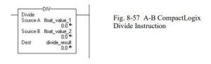
Divide
Divide float_value_1 by float_value_2 and place the result in divide_result.
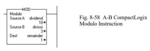
Modulo
Divide dividend by divisor and place the remainder in remainder. In the example, 3 goes into 10 three times with remainder 1. The value remainder is saved in the destination.
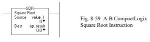
Square Root
Calculate the square root of value_1 and place the result in sqr_result.
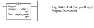
Negate
Change the sign of value_1 and place the result in negate_result.
Absolute Value
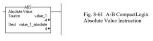
Place the absolute value of value_1 into value_1_absolute. In the example, the absolute value of
-4 is +4.
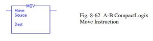
Move Instructions
Move (MOV)
The MOV instruction copies the Source to the Destination. The Source remains unchanged.
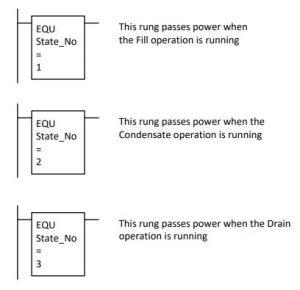
An Additional Look at the Juice Condenser
The Juice Condenser project was introduced in chapter 5 and discussed again in chapter 6. The juice condenser problem includes memory that the use of numbers encourage a new look.
The operation included a fill, a condensate portion and a drain. These operations were not to be overlaid but rather were to be consecutive. This leads to a memory circuit that includes more than one set of events.

Each memory circuit must be exclusive of the other two events and must occur in a proper sequence. For example, the fill operation must occur first, then the condensate operation and finally the drain operation. This may be expressed using a number representing the state of the operation. For example:
The three operations must be done in order. This requires that before the first operation starts, the requirement that there is not a fill, condensate or drain action presently active must be determined. This can be expressed in the start portion of the fill operation as:
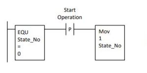
Succeeding operations must likewise be programmed using a start portion with the prior operation present.

The conclusion of this problem is left as an exercise.
Paper Making Process
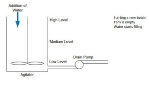
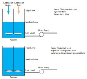
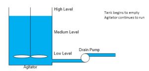
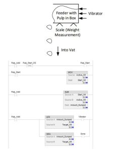
A process with logic, timers, compare and math is a mixing tank for making paper. The process works as follows:
- A tank is filled to medium level with water.
- The tank continues to fill with water and paper is added through a loss-in-weight feeder.
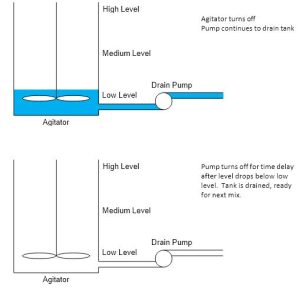
- A stirrer starts as soon as the paper begins to be added and continues until a batch is made and dumped and the level falls to the low level.
- The water finishes when the high level is reached and the paper finishes being added.
- The water and paper continue to be mixed until the paper is thoroughly mixed into a slurry by use of a timer.
- The tank is emptied by pumping the mixture out of the tank until the low level switch is reached. Then the process of making a new batch begins again.
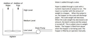
The most difficult part of the program is the control of the loss-in-weight feeder. The number is read as an integer and may be at any value in a range. The program is to start at this value, turn on an output and watch the number representing the weight decrement a set amount and turn off the output.
To start the program for the paper-making process, begin by providing a start-up rung. The rung must provide a memory circuit (probably a seal circuit) to start the process. The program uses an action by an operator to start the mixing operation. It is always good to check all the level switches for proper status but the low level switch is the only switch that must be checked for
proper level prior to starting. The low level switch must be off. The other two switches may be checked as well but are secondary to the low level switch for control of the batch. If either one of these two switches report a water level, the switch should be replaced or cleaned. It is not working properly or the low level switch is not working properly. Alert a maintenance person if this is a problem of any magnitude.
Where to begin the rest of the program is the responsibility of the programmer. Concentrate on one event at a time. Write down the requirements.
- First, water must be added
- Next, paper is added through a loss-in-weight scale
- Next, other ingredients are added
- Next, stirring occurs
When the paper pulp is to be added, start with a box of pulp and a vibratory feeder. Add the following:
Stepping Program for Machine
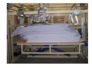
The following machine is similar to the conveyor of previous chapters except we now are filling a box with material coming from a process line. The name of this device is a festooner. The machine moves back and forth placing the material in the box. The box is weighed and when a weight is achieved, the box is full. There is usually an automatic knife that cuts the material and starts the material in a second box. The logic is similar to the previous conveyors in that there is a motor that drives the product to the right and then to the left. End of travel photo-eyes reverse the movement. The end of process is achieved when a weight is exceeded. A start button begins the action. Provide a .5 sec dwell when the photo-eye sees the product to stop the movement before reversing the motor.

The solution of this problem is left as a problem at the end of the chapter. A festooner is pictured below with no box included. The material is placed on the table without enclosure.
Number Systems
Decimal numbers
All number systems are positional in that each digit is weighted differently. For example, to write the number 287.54 represents 287.54 units of something. The 2 at the extreme left is the most important digit and is usually referred to as the most significant digit. The 4 on the right of the number is the least significant and is usually not as highly desired as the number on the left. For instance if 287.54 represented $287.54, we would be very interested if the number were
$387.54 or even $187.54, especially if this was a bill we were to pay. On the other hand, we could hardly care if the 4 at the right of the number were a 5, 3, 8, 9 or whatever. The weights of the number represent the following:
2 · 100 + 8 · 10 + 7 · 1 + 5 · 0.1 + 4 · 0.01
or:
2 · 102 + 8 · 101 + 7 · 100 + 5 · 8-1 + 4 · 8-2
Binary numbers
Binary numbers are used in microprocessors, programmable logic controllers, and in all digital circuits. The binary number system only contains 2 digits: 0 and 1. Each digit is called a ‘bit’ and can contain either the value 0 or 1. The binary number system is like the decimal number system a positional number system and is written in the same general manner as decimal except that 10x is replaced with 2x.
dn · 2n-1 + … + d4 · 23 + d3 · 22 + d2 · 21 + d1 · 20
Here dn is the nth digit (counting from right to left). If the number is an 8-bit number (called a byte), n is 8 (8 digits) and the binary number is 10101001, then it is calculated like this:
1 0 1 0 1 0 0 1
1 · 27 + 0 · 26 + 1 · 25 + 0 · 24 + 1 · 23 + 0 · 22 + 0 · 21 + 1 · 20
1 · 128 + 0 · 64 + 1 · 32 + 0 · 16 + 1 · 8 + 0 · 4 + 0 · 2 + 1 · 1
= 169 (decimal)
or
101010012 = 16910
Another example:
10011101
1 0 0 1 1 1 0 1
1 · 27 + 0 · 26 + 0 · 25 + 1 · 24 + 1 · 23 + 1 · 22 + 0 · 21 + 1 · 20
1 · 128 + 0 · 64 + 0 · 32 + 1 · 16 + 1 · 8 + 1 · 4 + 0 · 2 + 1 · 1
= 15710
or
100111012 = 15710
The radix of binary numbers is 2.
Hexadecimal Numbers
Hexadecimal numbers have 16 different digits (radix 16). The 6 first letters of the alphabet are used for the last 6 digits in the hexadecimal system. The digits are 0, 1, 2, 3, 4, 5, 6, 7, 8, 9, A, B,
C, D, E and F representing the decimal numbers 0, 1, 2, 3, 4, 5, 6, 7, 8, 9, 10, 11, 12, 13, 14 and 15 respectively. Upper case for A-F is optional.
The weights of numbers in hexadecimal is as follows:
dn · 16n-1 + … + d4 · 163 + d3 · 162 + d2 · 161 + d1 · 160
dn is the nth digit (counting from right to left). This is the same as in any positional number system. If the number is a 4-digit number, n is 4 (4 digits) and the hexadecimal number is 5A2E or:
5 A 2 E
5 · 163 + 10 · 162 + 2 · 161 + 14 · 160
5 · 4096 + 10 · 256 + 2 · 16 + 14 · 1
= 23086 (decimal)
or
5A2E16 = 2308610
Octal Numbers
The octal number system is used a little in plc texts and an explanation is as follows:
The octal number system contains 8 digits numbered from 0 to 7. To convert from octal to decimal, apply the following general formula:
dn · 8n-1 + … + d4 · 83 + d3 · 82 + d2 · 81 + d1 · 80
dn is the nth digit (counting from right to left).
A conversion of the octal number 2417 to decimal follows:
2 4 1 7
2 · 83 + 4 · 82 + 1 · 81 + 7 · 80
2 · 512 + 4 · 64 + 1 · 8 + 7 · 1
= 1295 (decimal)
or
24178 = 129510
Converting between the binary and hexadecimal numbers:
To convert from binary to hexadecimal, simply line the bits in 4 bit groups as follows:
10010111010110102
Binary 1001 0111 0101 1010
Decimal 9 7 5 10
Hexadecimal 9 7 5 A
or
10010111010110102 = 975A16
Hexadecimal numbers are usually easier to remember because they are shorter than binary numbers.
Another example:
E551A0F816
Hexadecimal E 5 5 1 A 0 F 8
Decimal 14 5 5 1 10 0 15 8
Binary 1110 0101 0101 0001 1010 0000 1111 1000
= 111001010101000110100000111110002
The table shown below summarizes the digits:
| Binary | Octal | Decimal | Hexadecimal |
| 0000 | 0 | 0 | 0 |
| 0001 | 1 | 1 | 1 |
| 0010 | 2 | 2 | 2 |
| 0011 | 3 | 3 | 3 |
| 0100 | 4 | 4 | 4 |
| 0101 | 5 | 5 | 5 |
| 0110 | 6 | 6 | 6 |
| 0111 | 7 | 7 | 7 |
| 1000 | 10 | 8 | 8 |
| 1001 | 11 | 9 | 9 |
| 1010 | 12 | 10 | A |
| 1011 | 13 | 11 | B |
| 1100 | 14 | 12 | C |
| 1101 | 15 | 13 | D |
| 1110 | 16 | 14 | E |
| 1111 | 17 | 15 | F |
Binary Addition
0 + 0 = 0
0 + 1 = 1
1 + 0 = 1
1 + 1 = 0 carry 1
1 + 0 + carry = 0 carry 1
1 + 1 + carry = 1 carry 1
These are the rules for binary addition. To see binary addition at work:
Carry 1 1 1 1
Number 1 0 1 0 0 1 1 0 1 1 0 0
+ Number 2 0 1 0 1 1 0 1 1 0 1 0
Results 1 0 1 0 1 0 0 0 1 1 0
Binary addition may take place in ladder logic. Instructions are provided to carry out this function (ADD), but it is worthwhile to examine the process of binary addition using ladder logic. In Figs. 8-35 and 8-36, logic to add two numbers using only combinational logic is shown.
Since Bit 0 does not have a carry_in, half-adder logic may be employed but only for this bit. It can be seen that half-adder logic is simpler than full-add logic by comparing Fig. 8-35 (Half- Adder) to Fig. 8-36 (Full Adder).
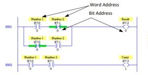
The number in location N7:0 is added to the number in N7:1. The result is stored in location N7:2. The carry is located in N7:3. The same locations are used for remaining bits of the word shown in Fig. 8-36. Full adder logic for each remaining bit from 1 to 15 is required. The logic must be duplicated for each bit. Carry_In is from the prior bit. The Carry_In for bit 1 is found in
Carry_Out of bit 0.
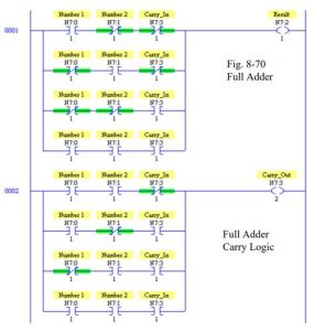
It is worth noting that to actually build this logic requires a great deal of time unless the Copy- Paste function is employed. Once the logic is built, changing the bit numbers in the logic is all that is required for succeeding bits from 2 to 15.
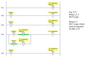
Binary Subtraction
To perform binary subtraction, the easiest method is to find the 2’s complement of the second number and then add the two numbers together. To find the 2’s complement, invert all the bits (1’s complement and add 1).
To find the 2’s complement:
number 0 1 0 0 1 1 0 1 0 1 1
1’s complement 1 0 1 1 0 0 1 0 1 0 0
+1 1
2’s complement 1 0 1 1 0 0 1 0 1 0 1
Then add the 2’s complement to the first number.
A second method of finding the 2’s complement requires the use of a memory bit. The rule requires that bits from the original number be copied to the 2’s complement number starting at the right-most bit. The rule applies until a “1” is encountered. The first “1” is copied but a memory bit is set after which the bits are “flipped”. Try this rule. It works and may be employed using ladder logic and a Latch bit to quickly find the 2’s complement of a number.
Again, logic must be added to complete the function using rungs similar to rungs 4 and 5 of this figure but using bits 2 through15.
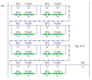
Binary Comparisons
To find if two numbers are equal, use the Equal Block. Use of combinational ladder logic may be employed as well. Using combination logic may be easy to employ but should not be used in PLC programming instead of the Equal Block. See below an example of the use of combinational ladder logic to determine if the number in N7:0 is equal to the number in C5:3.ACC. Notice that only the high bite or bits 8-15 are being checked for equality. If all bits are to be checked, the rung must double in size to check for the 8 additional bits (bits 0-7).
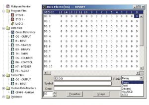
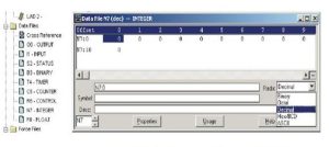
Radix
The term “radix” is used to describe the number base used to display numbers. For B3, notice the natural radix is binary although several other bases may be used.
Likewise, for integer numbers, decimal is the natural base used although any of the same group as binary can be chosen.
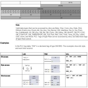
Accessing a “slice” of a tagged data type
PLC tags and data block tags can be accessed at the bit, byte, or word level depending on their size. The syntax for accessing such a data slice (Siemens) is as follows:
- “<PLC tag name>”.xn (bit access)
- “<PLC tag name>”.bn (byte access)
- “<PLC tag name>”.wn (word access)
- “<Data block name>”.<tag name>.xn (bit access)
- “<Data block name>”.<tag name>.bn (byte access)
- “<Data block name>”.<tag name>.wn (word access)
A double word-sized tag can be accessed by bits 0 – 31, bytes 0 – 3, or word 0 – 1. A word sized tag can be accessed by bits 0 – 15, bytes 0 – 2, or word 0. A byte-sized tag can be accessed by bits 0 – 8, or byte 0. Bit, byte, and word slices can be used anywhere that bits, bytes, or words are expected operands.
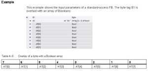
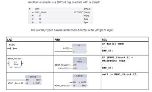
Accessing a tag with an AT overlay (Also Siemens)
The AT tag overlay allows you to access an already-declared tag of a standard access block with an overlaid declaration of a different data type. You can, for example, address the individual bits of a tag of a Byte, Word, or DWord data type with an Array of Bool. To overlay a parameter, declare an additional parameter directly after the parameter that is to be overlaid and select the data type “AT”. The editor creates the overlay, and you can then choose the data type, struct, or array that you wish to use for the overlay.
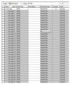
Allen-Bradley Data Slice
Below is an example of an expansion of a 32-bit word test_tag1 with the tag displayed as a DINT
and the bits addressed sequentially starting with bit 0 through bit 31.
Summary of Addressing Individual Bits
For a 16 bit integer, we have:
| Bit | 1 | 1 | 1 | 1 | 1 | 1 | 0 | 0 | 0 | 0 | 0 | 0 | 0 | 0 | 0 | 0 |
| 5 | 4 | 3 | 2 | 1 | 0 | 9 | 8 | 7 | 6 | 5 | 4 | 3 | 2 | 1 | 0 | |
| Siemens M | 0 | 0 | 0 | 0 | 0 | 0 | 0 | 0 | 1 | 1 | 1 | 1 | 1 | 1 | 1 | 1 |
| . | . | . | . | . | . | . | . | . | . | . | . | . | . | . | . | |
| 7 | 6 | 5 | 4 | 3 | 2 | 1 | 0 | 7 | 6 | 5 | 4 | 3 | 2 | 1 | 0 | |
| Siemens Addr | . | . | . | . | . | . | . | . | . | . | . | . | . | . | . | . |
| x | x | x | x | x | x | x | x | x | x | x | x | x | x | x | x | |
| 1 | 1 | 1 | 1 | 1 | 1 | 9 | 8 | 7 | 6 | 5 | 4 | 3 | 2 | 1 | 0 | |
| 5 | 4 | 3 | 2 | 1 | 0 | |||||||||||
| Logix | . | . | . | . | . | . | . | . | . | . | . | . | . | . | . | . |
| 1 | 1 | 1 | 1 | 1 | 1 | 9 | 8 | 7 | 6 | 5 | 4 | 3 | 2 | 1 | 0 | |
| 5 | 4 | 3 | 2 | 1 | 0 | |||||||||||
| SLC | / | / | / | / | / | / | / | / | / | / | / | / | / | / | / | / |
| 1 | 1 | 1 | 1 | 1 | 1 | 9 | 8 | 7 | 6 | 5 | 4 | 3 | 2 | 1 | 0 | |
| 5 | 4 | 3 | 2 | 1 | 0 |
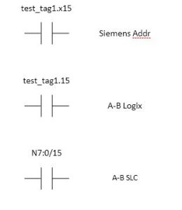
Data Slice Last Look
With the above table, we can assign contacts or coils referencing specific bits in the word
test_tag1. These examples show addressing for the most significant or sign bit.
Summary
In summary, the chapter discusses manipulation of numeric data in the PLC. Math Function Blocks were described first. Math Function Blocks replace the relay coil at the right of a rung. Execution of the function block happens with either regular or one-shot contacts. The Math Function Block may also be programmed to execute continuously.
Compare Instructions allow power to pass in a manner similar to relay contacts. A Compare Instruction, LIM, was discussed and found to control a contact over a range of numbers.
Comparison Instructions with memory were used to provide a dead-band for switching on or off an output. Various memory circuits were demonstrated in programs to provide this control algorithm.
The Status Table in coordination with math operations was discussed. Several Status Table locations described the use of math operations and locations of math holding registers. Thirty- two bit integer math was briefly described. The status table is also used to control the 32-bit math operation. Floating point math as well as floating-point_integer math instructions were also discussed.
The SCP or Scale with Parameters Instruction was summarized. A method of protecting against numeric overflow was described. ADD and SUB blocks to add or subtract 1% or 5% from a number were also programmed.
Use of Instruction Help with the example of the CPT block was also given. Logic was developed showing the mixing of logic for counters and math.
A paper-making process was described with many implications for the use of math in PLC logic.
Various number systems were described including decimal, hexadecimal and octal. The Radix box in RSLogix 500 was described.
