
9 Planning the Panel
Introduction
When installing a PLC for use in a control panel and for a factory floor application, the total hardware configuration must be considered. Questions such as how the PLC will fit in the panel, what to include, and how to wire it must be considered. Power must be furnished to the components at the correct voltage and sufficient current. The environment of the control panel may need to be considered as well, whether it will need heat or coolant, protection from moisture or other foreign material. Power may be furnished to the control panel at 120 VAC. Voltage may be exposed at terminals if the design is not finger-safe. Other control panels use 24 VDC exclusively. A majority of student trainer models use 24 VDC since it is much safer for the student to wire I/O without much fear of electrical shock. Trainers used in schools usually have a 24 VDC power supply.
Other devices found in control panels and on most trainers are terminal strips, push buttons, pilot lights, switches, a safety disconnect switch, and of course a PLC. Some control panels have a MCR (master control relay) which has the purpose of shutting down the entire panel if the MCR is not engaged. Most trainers and control panels have either fuses or circuit breakers for circuit protection.
This chapter discusses several issues to be considered when building the automated control application. Included in the chapter are discussions about wire and voltage type. Interfaces between different control elements are also discussed. Safety is reviewed at the panel level as well as at the project level. Standards for drawing generation and drawing types are included as well as an introduction to the AutoCAD Electrical productivity enhancement program.
An aside about 24 VDC used in the factory:
This voltage is very popular as the control voltage of choice in Europe. Some automakers have adopted 24 VDC in the USA as a standard for control applications since only one maintenance person is initially needed to fix a machine problem. While an electrician and a machine repairman are required with 120 VAC machine problems, low voltage DC requires only one common repairman to fix most down-time problems.
With the newer Arc-flash rules in place, 24 VDC has become the dominant voltage for most control circuits. The 115 VAC circuit is soon to be gone (or at least in many applications).
Begin with the Steel
Every control panel must include the steel (or composite material) to house the electronics. The following are a sampling:
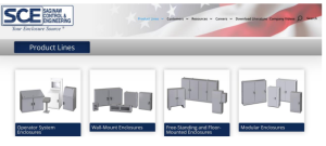
The advertisement below from a distribution company McMaster Carr shows the variability in purchasing of electrical enclosures. Hoffmann, Wiegmann are two standards. Others provide similar product lines. You can buy an electrical control panel through Amazon as well as Zoro, Digi-Key or Automation Direct. As with all purchases of this kind, do not forget to include the back-plate since it many times is quoted separately.

The Rittal company was introduced to the American market in the 1980’s and began a trend away from the individual custom panels to a build-by-section platform. They have been very successful in this.

A company in Ann Arbor, Michigan, Dynics, recognized that to gain acceptance on the factory floor, their software and computer skills would be greatly enhanced by supplying the end user with a computer, HMI screen or other automation product by enclosing them in a steel panel and selling the package as a unit. Software and Steel has proved a success for them.

Dynics is a success by recognizing the simplicity of supplying what the customer needs – a panel complete with software. This is a dedication to the ingenuity of the company and its leadership. They are highly recommended!
Temperature and Humidity
Rules for construction of a control panel were first discussed in Chapter 2 – Ladder Basics. This chapter (Planning the Panel) concentrates on issues that must be considered if the PLC application is to work properly. For example, it is important to consider the temperature inside and outside the control panel housing the PLC. When the panel enclosure is installed, the temperature might be in the 70 degree range. However, during the course of a year, many enclosures are subjected to very hot or very cold temperatures causing electronics to potentially fail. If a panel is not adequately heated in northern climates, the electronics will stop working. Interestingly enough, the panels controlling oil through the Alaska pipeline were not heated. They are very well insulated however, and the heat from the PLC was adequate to keep the PLC and the other enclosure contents running. If one of these PLCs lost power, it was very difficult to re-start the panel since the power supply attached to the PLC would not turn on if the temperature was very low. Electricians used blow torches to heat the panel until the PLC was warm enough to restart. Heat generated from the power supply warmed the electronics inside the panel. Then the door could be closed and the system restarted
Moisture and humidity may be a problem as well. Remember that water condenses at the surface of a wall where hot moist air meets cold dry air. If this occurs, the outside or inside of a panel will sweat and accumulate water. Also, water may enter a panel through conduit from above based on the same condensation process. Use of water barriers helps protect a panel from this situation. Meyer Hubs are a specific type of conduit condensate protection. If a food application is being planned, do not forget the use of water hoses on a panel. The best panel must be well planned to protect from the effects of high pressure water spray.
Terminals
Ground is used as a reference in most PLC systems although un-grounded PLC systems are found in plants using an ungrounded power source. Ungrounded electric control systems are accepted by the National Electric Code as well as grounded systems and are a requirement for the PLC manufacturer to provide adequate wiring constraints for these systems.
A common rule for ground lug design is to provide only one location for devices to electrically terminate. Disregarding this rule may set up a loop for grounds. Ground loops are not a good design since currents can travel in ground wires causing changing voltages between ground references. A good practice is to tie all grounds in a panel to one common grounding location and then tie that ground lug to the building ground grid. Remove paint between connectors so that current can flow easily within the grounding system in the panel and to the ground lug.
Terminals are used to connect wires in a panel. Usually, one side of the terminal is reserved for field wiring and the other side is for the internal panel wiring. Care must be taken to size all internal wire-duct sufficiently wide and deep enough to fit all wires in the wire duct and also to fit all covers on. Terminals may be stacked, jumped, and grounded. However, do not use terminals too small for the electricians’ screwdrivers since these individuals may have difficulty successfully terminating the field wires for the PLC panel. Electricians tend to carry small screwdrivers and will terminate most small-gage wire but it is always courteous to inquire of company preferences prior to final design of a panel.
Since wires can carry current of sufficiently high value to induce voltage on adjacent wires, care must be taken to not allow AC and signal DC to lie in parallel panel duct. When these wires cross, they should cross at a 90 degree angle. Also, use surge suppressors on inductive loads to dampen or suppress noise in adjacent I/O.
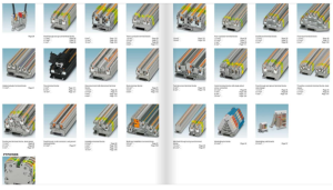
Examples of various types of terminal blocks are shown above in the Phoenix Contact Terminal Block Catalog.
Use of Surge Suppressors and Bleed-off Resistors
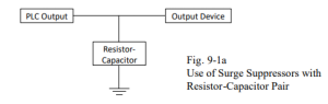
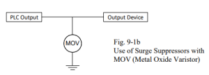
MOV’s (metal-oxide-varister) are similar to zener diodes and are rated for a specific energy or voltage peak. MOV’s are one group of a variety of surge suppressors. Another form of surge suppressor is the RC (resistor-capacitor) snubber. Either the MOV or the RC snubber may be used to decrease current spikes in the PLC circuit. They are attached as follows:
A MOV device is attached in a similar fashion to the Resistor-Capacitor pair as follows:
Drawing Practice
The wiring must be drawn as a document for future use. Drawings may be initiated on a drafting board or in a computer using a CAD package. Many packages exist to generate panel lay-outs and, in particular, PLC I/O. In the CAD package, the device external to the PLC is stored with a symbol name or accessed from a tablet with the symbols present. Then, the wires are assigned numbers and the I/O is assigned as well. Wire numbers are essential in any large job since a wire may go to many different locations and must be identified in each location. Usually, panel locations are displayed as small symbols above or below the device in attached to the I/O point.
From the CAD package or the PLC programming software, a list of I/O can be developed. This list is necessary to adequately prepare the wiring drawings and finish the program. The program listing and the I/O sheets must agree with inputs and outputs matching the program-listed I/O.
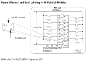
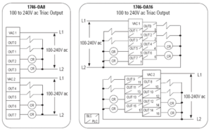
Even though most Allen-Bradley cards are shown with the following type of layout in the literature, cards may be arranged in a more ordered manner for use in a schematic. Allen- Bradley’s layout of the 1746 IA16 card is shown below.
From the layout above, one approach to layout the drawing would be to use the layout below to draw the control diagram.
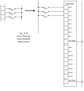
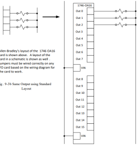
The following two figures show samples of the resultant I/O drawings with inputs and outputs wired to various PLC points as part of a PLC ladder diagram. These samples show only a small portion of the overall wiring of each of the total card layout. Notice the addition of wire numbers and I/O addressing in these samples:
In addition to having wire numbers and I/O addresses, many PLC schematics also include terminal designations for devices with terminals having specific assignments. Location designations are also indicated on the schematic in many cases to specify the location of a particular device.
Leakage Current
When matching inputs from one PLC to outputs of another, care must be taken that the leakage current of the output is not sufficient to turn off the input even though the output is off. To guard against this occurrence, a bleed-off resistor adequately sized to carry the leakage current to ground is needed. Using the formula for Ohm’s Law V = I*R will give the proper value for R. Leakage current is listed for most outputs. Use the leakage current value for I. Voltage is the operating voltage of the output.
For example:
V = 115 VAC
I = 1 mA
R = 115/(.001) = 115 KOhm
Power rating of the resistor:
P = I*I*R = (.001)*(.001)*(115 K) =.115 (or less than 1/4 watt, a common wattage for resistors). Having a supply of 100K, ½ or ¼ watt resistors is always a good idea when starting-up equipment and potentially confronted with this type of problem.
See Fig. 9-5 for placement of a bleed-off resistor in a PLC circuit:
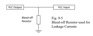
Leakage is most common in the triac output. The circuit above is very useful if the triac leakage current is enough to turn on the input circuit attached to the triac output. This will occur if the input impedance of the device is high enough to not require current greater than the bleed-off current of the triac output.
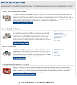
Families of I/O Cards
Several types of PLCs and I/O are available. For Allen Bradley and Siemens, these families of processor and cards are found on their respective websites. The choice of a processor type will determine the choice of I/O cards available as well as a layout of the system. Spare cards must be considered when choosing the PLC since one card of each type should be ordered as a system spare.
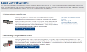
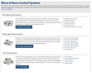
The Allen-Bradley family of PLC types is shown here including large, small and micro/nano systems:

Shown here are the Siemens’ families of processors. The smaller S7-1200 is followed by the S7- 1500 and 300 and 400 processors:

Shown below are the distributed processors offered by Siemens. Included in the distributed controllers are processors that need no panel in order to operate in the plant environment:

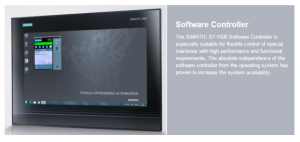
Siemens also offers a software controller in the S7-1500 family. In this configuration, the controller and HMI are bundled together in the same unit.
Most PLC vendors also have a list of legacy products the manufacturer supports. When chips used in the design of a particular PLC are no longer available, most vendors are unable to support their legacy product list. Then the products can only be bought from third-party vendors (including E-Bay).
Not shown are products that are coupled to the PLC to make a complete system. Items such as HMI screens, motor control drives and other devices make a system that will be used to control a process.
Wiring of AC I/O Points
For AC circuits, wiring is straightforward. Wire from an output of the sensor to the input of the PLC. Wire from the PLC output directly to the output device.
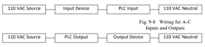
There are few differences between manufacturers since most AC devices respond to a high input with an on or 1 value. Neutrals are included in most circuits to give the circuit a proper 0 V reference value.
While wiring of PLC AC inputs and outputs is not difficult, testing of the device to determine its status in many cases is difficult. With any industrial environment, noise is a constant problem and while ‘on’ is usually seen as a reading of 110 V on your favorite DMM, ‘off’ may not read 0V. In fact, the DMM may read values almost up to about half the actual voltage of the system even with the output off. Off may be the state being read but noise may be present giving values that are far from 0. If the application is near an arc melt steel furnace, values seen while the triac output is off may range into the 40 to 60 VAC range. The key feature of the reading when an output is off is that it is not consistent. That is, the values move around with no stable reading for more than a second or two.
Wiring of DC I/O Points – Sourcing and Sinking
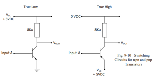
To better understand sourcing and sinking terminology in DC applications, remember the npn switching circuits from a solid state circuits course. When the npn transistor is used as a switch, IC is maximum when VCE is minimum. From the bipolar junction transistor, the load line graph is as follows:
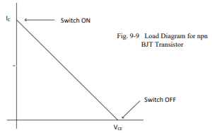
True high refers to sourcing which is opposite of the graph above. When current is on with true high, voltage is high. Another term used in conjunction with true high and sourcing is pnp which refers to the type of transistor used in true high circuitry.
True low refers to the npn transistor with load line shown above. The two types, True High and True Low may be summarized as follows:
Sourcing or -on with High Voltage, Current On
True High: -off with Low Voltage, Current Off
Sinking or -on with Low Voltage, Current On
True Low: -off with High Voltage, Current Off
An alternate name for True High is Sourcing or pnp and an alternate name for True Low is Sinking or npn.
A switching circuit using the npn transistor is shown below. In this circuit, when input A turns on or high, Vout sinks to low or close to 0 volts. The transistor conducts. This is an example of a simple True Low circuit. A switching circuit using the pnp transistor is also shown. In this circuit, when input A turns on or high, Vout turns on to 5V. The transistor conducts. This is an example of a simple True High circuit.
Care must be taken to provide proper connections between output leads from one device and input leads to another device. If one device is true low, the other device should be capable of accepting that signal. Usually true low devices connect together as do true high devices.
Indiscriminate mixing of devices may lead to trouble because of differences between sinking and sourcing circuit characteristics. It is always best to review and analyze the circuit to determine if devices are at high voltage (Vcc ) when they conduct or turn on and conduct at low voltage near 0V.
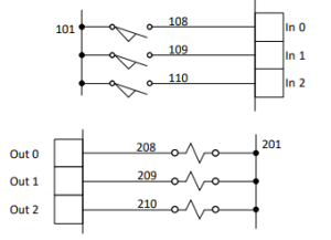
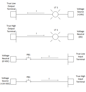
The following four circuits show true high and true low inputs and outputs attached to the PLC. If a True Low output from a PLC is wired to turn on a light, the first circuit may be used. If a High output from a PLC is wired to turn on a light, the second is used. If a True Low input to a PLC is wired from a device, use the third circuit. If a True High input to a PLC is wired from a device, the fourth circuit is used.
Wiring in Panels
While students are usually interested in programming the PLC and solving the logic associated with turning on devices, the work of designing the panel for housing the PLC and the other equipment necessary to run the process may be considered an after-thought. Care must be taken to properly lay out the panel for maximum use of the interior of the enclosure while giving enough room inside for the equipment and wiring. Panel builders are experts at layout of a panel and should be given some latitude in the construction of panels. However, common sense should be applied by the engineer when planning the layout of a panel.
- Enough room should be allowed in the panel for a terminal strip along one side.
- Panduit or wire-way should be laid out on both sides of the terminal strip. One side should be left empty so the field wiring has sufficient room for entry into the panel through this wire-way. The other side should be wired to the terminal strip from the PLC or other devices as needed.
- Circuit breakers and other devices in the panel should be properly labeled corresponding to their name on the electrical schematic.
- AC wiring should be separated from DC wiring.
- Analog wiring should be run in separate wire-ways and away from AC and discrete signal DC wiring.
- When analog wiring must cross other wiring, it should cross at 90 degree angles.
- Analog wiring should, in general, not be terminated except at the PLC. Do not use terminal blocks for intermediate terminals for analog.
- Vendor specifications should be thoroughly reviewed for heat and cold limitations. If the panel is to be located outside or in a non-heated building, the panel may need to be heated with a small heater under thermostat control.
The layout on the next page shows a grid of a panel. Notice the room allocated to Panduit-type wire-ways and terminal strips. Panel size is always an important decision. It is best to not make the panel too large. Remember that a larger panel costs more to make and requires more space on the production floor. However, also remember that an undersized panel can cause great pain later if there is not enough room to add changes that may become necessary later on. The trade- off between having sufficient room and having too much room is a difficult one.
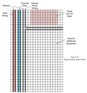
Layouts are accomplished best on a grid. When equipment is placed on a grid, use 1, 1.5 or 2- inch grid lines to layout the panel. Do not forget the distance between terminal strip and wire- way. You may be the one who must move a wire or terminate a wire under one of the terminals in the panel. If your fingers can’t put the wire in the terminal, then the wire-way is too close to the terminals. Include a back-plate when purchasing a control panel. Back-plates may or may not be sold with the panel but are needed since devices tend not to be mounted directly to the shell of the panel. Hoffman and Hammond are two panel enclosure manufacturers. Terminal blocks are made by a number of companies including Phoenix Contact, Entrelec and Weidmuller. Design of the terminal strip includes devices mounted on a DIN rail of the terminal strip. Included devices are isolation devices that are DIN mountable as well as some small power supplies that are DIN mountable. DIN mounting rail is used in almost all areas of a panel to mount devices including the PLC itself.
Tap Rules
Determination of wire size in a panel as well as to field devices deserves consideration. Wire size is determined in general by the current load of the wire and the insulation rating of the wire. The National Electric Code includes tables for determining the proper size of wire for all electrical applications.
Usually, #14 AWG (American Wire Gage) or #16 AWG wire is sufficient for panel control wiring. Number 18 AWG cable wiring is also used from time to time. Wiring to motors and other control devices must be sized for the application. In general, a power feed is brought into the panel and fuses or circuit breakers are used to distribute the load to each of several circuits in the panel. It is important to note that for AC circuits, use of 220V distribution panels (as used in most home applications) is not considered good practice in a control application. The use of two sources of 110 V that are 220V apart may cause accidents that could be avoided if only one source of 110V power is used. Many times, in the heat of the moment, an electrician may be trying to restart a system and jumper a source of 110V into a circuit. If the circuit is already powered from the opposite 110V source and a contact closed between the two sources, a contact could see 220V of electric energy. The consequences are usually colorful. Contacts may weld closed as well, not a pretty sight.
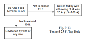
The National Electric Code also permits feeder taps that comply with the 10 and 25 foot tap rules. These two rules are common to electric installations and provide convenience for electrical installations using terminals to distribute electric power to a number of devices. These two rules allow the tap feeding a device to not be rated at the current rating of the tap but at the rating of the device being fed.
The 10 foot tap rule allows any size wire to be used to tap from the source while the 25 foot tap rule allows for wire to be used to tap from a source that is rated 1/3 or more of the rating of the tap. These two rules are summarized in Article 240-21 (b) Feeder Taps in the 1999 NEC. Other sections amplify the tap rule for taps supplying transformers and for conductors outside the control panel. The rules should be read carefully and applied for all electrical installations. The tap rules allow for distribution of electrical power in a control panel in a practical yet safe manner. An example is shown in the figure below:
PLC I/O Loading
Care must be taken to adequately provide power for all inputs and outputs in the system. Many times, this isn’t a consideration until a power supply starts to turn off frequently or fuses continue to blow or circuit breakers trip. Care should be taken to avoid these events from occurring. Also, care should be taken to not provide so much power that the system is unnecessarily increased in size and costs increase proportionally.
When an input is wired to the PLC, the current draw of the input device is determined not only by the type of input device but also by the input impedance of the PLC. The current draw of each input is then added together to calculate the total current draw for inputs. If the input is a switch, the current draw is found using the input impedance of the PLC. If wire lengths are extremely long, then the resistance of the wire also is included. Do not forget to double the length since current travels out and back to the device.
As confidence builds in sizing current loads for devices, some approximations can be used. For example, at 120 Vac, a solenoid valve output device usually draws about .2 A per device when on. When energizing, the device draws about 1 A for a short period of time until the device is seated in the ‘on’ position. As long as large numbers of solenoids do not turn on at a time, the .2
A. draw can be used for calculations.
From the 1761 MicroLogix 1000 User Manual, the input specifications for the MicroLogix inputs:
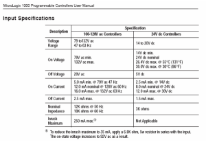
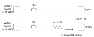
From this specification, it can be seen that the input for a 24 V dc input is 3K ohms.
When an output is wired to the PLC, the impedance of the output device must be known or approximated. From the 1761 MicroLogix 1000 User Manual, the output specifications for the Micrologix outputs:
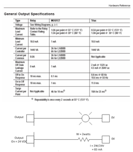
Load is determined by the device attached to the output. Remember the example of the solenoid. Notice that A-B takes a bolder approach regarding leakage current and recommends a 15K 2 W resistor. This value will definitely drain the 2 mA of leakage current. Two 100K ¼ W resistors will also do the job.
Relays
Relays are used in many applications as interface devices between the output from one system and the input to the PLC or from the PLC output to a second system’s input. While relays may be a good choice for this type of interface, caution should be taken when using them.
The duty or loading of the relay should be considered when choosing a relay. Duty may range from heavy, intermediate, low level loads or dry contact loads. A dry contact is described as a contact load in which no switching occurs under load. For any loaded switching device, some arcing occurs each time the device is switched. Care must also be taken to choose a relay that will not switch off to on more times than the rated number for the relay. Also consider current level of the relay and the coating on the relay contacts. Silver-cadmium oxide easily handles high currents but tends to fail at low current levels. Gold alloys are more suited to low current levels but are not acceptable at high currents. If the current rating required for the relay spans both low and high current ratings, results may be other than acceptable.
The following example identifies potential problems with using relay contacts for switching loads. “There is no relay contact that can be used for switching all load levels. Each load level requires tailoring of the contacts for that specific application.” The example shows the inadvertent misuse of a relay and the consequences of the misapplication. The following is from a Navy or Navy Allocation and Resources Model (NARM) document.
“DOWN TO THE SEA
In spite of the early hour, a small audience witnessed the departure of the submarine on its training voyage. Wives and friends along the channel waved their farewells to the crewmen still on deck. At last they were past the breakwater.
A klaxon signaled ‘dive’ and the topside crew vanished. The last hatch cover clanged shut. Then silence except for the throb of the diesels as the sub sailed on. And on. And on. And on.
We won’t describe the language that shattered this placidity once it was realized that the sub definitely refused to submerge.
WHERE DID IT ALL GO WRONG?
Back at the base, the failure was traced to a DPDT, 1/2 crystal can relay in the dive control circuitry. We received the relay and a 4-page, typed, single- spaced (but friendly) letter shortly after.”
The Navy story goes on to describe the aftermath of the sub’s mis-adventure. In the analysis that followed, it was discovered that the 2A dry contact relay did not pass current at low current levels. The gold alloy plating had burned off the contacts due to a high current when the relay was used to turn on a lamp. Surge currents when the lamp was first energized were high enough
to effectively burn the gold plating from the contacts and cause the relay to fail.
Proper selection of relays to interface circuits is an important consideration. Care should be taken to properly protect contacts from dust and improper usage. From the Navy’s experience, if a contact is used for one set of conditions, it should not be expected to then be used for a very different set of conditions. Since relay use is part of any PLC installation, proper selection of relays is needed. Just ask the Navy.
An alternative to selecting a relay is to provide a solid state switch to interface various devices. Since the switch must be terminated, a circuit board must be provided and various power levels provided. Since the complexity of such installations can grow and cause maintenance problems, the usual recommendation is to select a relay. If a module can be found that does not include contacts, however, the solution should be considered since problems with relays and relay contacts are non-trivial.
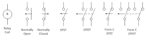
The view below is of an electromechanical relay or EMR used in many applications. Contacts arrangements are reviewed below as well. The relay pictured is the “Form C-DPDT”.
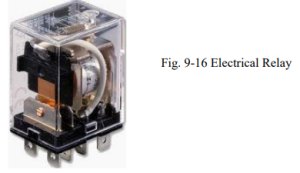
The relay above works based on the magnetic force produced by the magnetized core attracting the moveable contacts connected to the pivoting arm shown. The Form-C contacts are shown in the figure below.

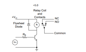
The figure below shows a relay turned on and off from a transistor switching circuit:
Shown below is a solid-state relay used to turn on a triac or ac switch:
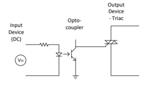
Solid state switches are designed for turning on and off at the zero cross-over point of the sine wave allowing only minimal inductive or capacitive interference with the circuit. Still, it is wise to use a MOV or RC snubber circuit when turning on output devices.
While this is not a magazine advertising products, these two manufacturers should be considered when building a control panel. Both, Phoenix Contact and Red Lion have a special place in my heart since I have used both extensively when designing panels in the past.

AutoCAD ELECTRICAL 20xx
First introduced in Chapter 2 and reviewed in more detail here is the electrical productivity improvement package, AutoCAD Electrical 20xx. The package has been popularized to the point that most electrical engineering majors need some experience in using it prior to entering the workforce. The package is extremely popular in the Pacific Rim area as well as in Europe and the US. It should be considered especially by those selling to or interfacing with companies trading in any of these areas.
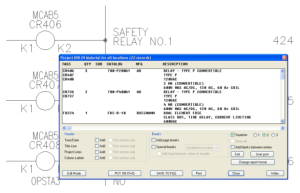
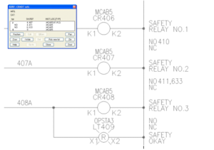
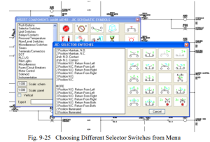
Generating of electrical schematic drawings can be a very repetitive task. AutoCAD Electrical uses AutoCAD and the electrical package enhancement to design a new system and create all components necessary for building the control panel and all schematic and wiring drawings. A number of example solutions will be used to show the power of this approach. Shown are a number of electrical schematics with AutoCAD Electrical 20xx used as the drawing generation package.

The drawing shows a sample ladder diagram being constructed using AutoCAD Electrical 20xx. Basic choices from the Tool Palette are:
- Schematic – placement, tagging, and cross-referencing of sensors, switches, relays, terminals, and PLC I/O modules into the ladder diagram
- Panel – physical layout of components in control enclosures
- Wires – insertion of interconnected wiring and wire number assignments
The reason for using this type of software package is to reduce complex tasks that are repetitive into simpler tasks.
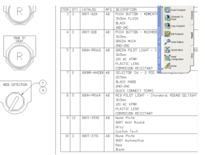
Creating a Bill of Material
Above shows the bill of material (BOM) generated as a schematic drawing is created. All the information about each component necessary for the job is logged. Generated with the schematic drawing are terminal strips showing wiring of each terminal with applicable wire numbers along with locations of the devices. A catalog of components is included for the designer to automatically scan. Catalog numbers are stored for devices from most major vendors including Allen-Bradley, Square D, Siemens and others. This allows for quick look-up and cross-referencing of an electrical part for inclusion in the design.
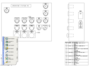
Creating a Panel Layout
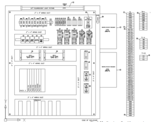
The figure above shows an example of a panel layout. As components are changed in one drawing, they are automatically updated in all associated drawings. This effectively increases drafting productivity. Checking for missing components is eliminated since there is a link between parts on schematic drawings and panel layout drawings.
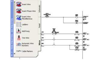
Using the Wires Tab:
- Insert Wire
- Insert Multi-Phase Wire
- Insert Wire Miscellaneous – special wire tools
- Ladders
- Add Rung
- Trim Wire
- Automatic Wire Numbers
- Cable Markers
Authority Having Jurisdiction
There are a variety of AHJ individuals for a local area. AHJ is short for Authorities Having Jurisdiction (AHJ). They in general use the latest versions of the National Electrical Code® (NEC®) which at present is 2011 and 2014. The requirement is that industrial control panels be marked with a Short Circuit Current Rating (SCCR) and the AHJ will be checking to be sure that the panels in a new install will be marked appropriately. Since 2006 all UL Listed industrial control panels are now marked and labeled with a Short Circuit Current Rating. The Short Circuit Current Rating is the maximum current the control panel can safely withstand without excessive damage. If the available fault current of the electrical system where the panel is installed exceeds the SCCR of the panel and a short circuit occurs, catastrophic damage to the panel may occur and electrical workers and others are put at risk of injury. These rules are new and not all controls engineers have heard the extent of these changes or, perhaps, decided that the changes are for them.
It is the responsibility of the consulting or electrical controls engineer to verify that all industrial control panels are applied in a manner such that the panel’s SCCR is greater than the system’s available fault current. It is the responsibility of the industrial control panel manufacturer to provide accurate SCCR information to the consulting engineer and the Authority Having Jurisdiction through required labels.
Once the panel is in place, care must be taken with regard to entry of the panel. If the panel is rated with a SCCR with sufficient voltage (>50Vac), it may be entered only by qualified persons or unqualified persons that have been advised and are escorted by a qualified person. This rule is outlined in NFPA 70E-2012 Ch. 1, Section 130. The individual is required to use shock protection techniques and PPE clothing. The distance requirement is determined to protect individuals from 2nd degree or higher burns. The ratings and applicable equipment will be called out in the various parts of the current NEC code as well as NFPA 70E and UL 508A. The suit shown below is a worst case scenario for troubleshooting live electrical components with the new rules:

What is required to make the control panel safe for use?
The following three steps define the procedure to follow to design a safe panel:
- Determine the Operating Voltage of the System
- Determine Shock Protection Boundaries
- Determine the Personnel Protective Equipment
To be able to not need the NFPA 70E rules, the panel and contents must not have components operated at greater than 50 Vac. Otherwise the rules below apply.
The boundaries for shock protection are shown in NFPA 70E-2012 Ch. 1, Section 130 – Table
130.4 partially shown below:
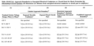
The boundary of approaching a panel is to be marked in accordance with NFPA 70E. The table defining the boundary is only partially shown above and shows the extent of the rules concerning the boundaries around panels.
Jim White, Shermco Industries, writes the following concerning updates to the new edition of NFPA 70E:
“Once again the NFPA 70E Committee has made significant revisions to the table method in the 2018 edition of NFPA 70E Standard for Electrical Safety in the Workplace. Since the 2000 edition of NFPA 70E the task tables have been both a boon and a bane. They were a boon, because in the absence of an incident energy analysis, the tables were often the only method available to choose arc-rated clothing and PPE. They were a bane, because they were difficult to use in the field and reduced the Hazard/Risk Category (HRC) number by 1, 2 or 3 numbers based on perceived risk.”
We see with the new NFPA standard a change in some design parameters as those listed in the partial Table 130.5(c) table below:
There has been a relaxation of arc flash PPE requirements on unlabeled equipment at maximum 120VAC unless there is reason to believe the available fault amps are dangerous.
Shock hazard PPE is required above 50 VAC up to 150 VAC with the approach boundary being defined as “avoid contact”. In other words, if you intend to touch live parts, wear voltage-rated gloves. (Alfred Craig, JDI Group, Toledo, Ohio)
We see that the threshold is now 125 Vac for working on a panel without PPE gear. Notice that the change from 2012 to 2018 may change again. This signals that the prudent see each new edition of NFPA 70E as a new read and their responsibility to be aware of those changes that may occur.
Determining the SCCR
The method for determining the SCCR or Short Circuit Current Rating is to apply the standardized tables of UL508 A standard for industrial control panels. SCCR calculations may be somewhat ambiguous at times and consideration of future changes may be necessary in determining the SCCR. In many cases, the corporation has decided to have a consultant determine the SCCR at various points in the facility. A one-line electrical drawing is left which records these ratings and is kept up-to-date as changes take place in the plant.
As stated earlier, every electrical machine or system in the USA may be checked by an inspector known as the AHJ (Authority Having Jurisdiction) before it can be commissioned. Acceptance is based on the NEC (National Electrical Code, also known as NFPA 70), the relevant application- specific guidelines such as NFPA 79, as well as any local standards or specifications.
Some control panels may be required to be certified by UL as well. Some states may require UL approval of a panel. Manufacturing an industrial control panel that meets UL requirements is more than a question of simply using UL-approved products.
To receive a panel UL certification, an approved panel builder may be used. They need to comply with various conditions in order to do this. The panel builder’s workshop is visited several times a year by a UL inspector and checked for practices in accordance with UL 508A. Some of these visits will be announced but others will not. The panel builder then pays an annual fee plus the charges for the UL inspector’s visits. Other options may include having a UL inspector officially review the panel at time of construction and apply the UL sticker.
The industrial control panel may also be inspected on-site by the AHJ and accepted by a local inspector at each place of installation. In other words, the manufacturer relies on the opinion of each inspector. Complaints then have to be remedied on site. Usually, the arrangements of inspection are part of a contract or are arranged by someone other than the control engineer.
Sometimes this process falls under the job of the project manager or construction manager.
The Panel Label
The industrial control panel shall have the following information (minimum requirement):”
- Name of the manufacturer
- Full electrical characteristics for each incoming feeder
- Field wiring diagram number or designation
- Place of manufacture (only if the manufacturer produces industrial control panels at various locations)
- Industrial control panel degree of protection ≙ Enclosure Type rating
- Short-circuit current rating (UL 508A SB5.1 and NEC 2008 Art 409.110)
- Warning of hazardous arcs (Flash Protection – NEC 2008 Art. 110.16 and NFPA 70E)
- Field connections: Power, control current, grounding, neutral
- Fuse table along with class and size of fuses
- Cautionary markings, e.g. multiple feed-ins, capacitor discharge, electric circuits that are not deactivated by the main disconnecting means.
- All devices which are not part of the industrial control panel but which have to be connected to the panel at the site of installation (e.g. circuit breakers). For other markings, see UL 508A Table 52.1.”
Short Circuit Current Rating of the Control Panel Power Circuit
An industrial control panel must be marked with a SCCR – Short Circuit Current Rating. NEC 2008 Art. 409 describes the specifications of short circuit current rating mark on industrial control panels (with reference to the UL 508A, SB4). For short circuit rating, not only the short circuit breaking capacity, e.g. of the circuit breaker, but also the short circuit rating of every individual device in the power circuit is relevant. The SCCR-relevant components in the power circuit include circuit breakers, contactors, overload relays, solid-state switching devices, terminals, busbars, the line side of control transformers and frequency converters.
Need for SCCR – Arc Flash

What Is Arc Flash?
Arc Flash Injuries:
- Electric shock
- Severe burns
- Blindness
- Blast injuries
- Shrapnel wounds
- Lung blast injuries
- Ruptured eardrums
- Pressure wave injuries
Arc Flash is the result of a rapid release of energy due to an arcing fault between a phase bus bar and another phase bus bar, neutral or a ground. During an arc fault the air is the conductor. Arc faults are generally limited to systems where the bus voltage is in excess of 120 volts. Lower voltage levels normally will not sustain an arc. An arc fault is similar to the arc obtained during electric welding and the fault has to be manually started by something creating the path of conduction or a failure such as a breakdown in insulation.
The cause of the short normally burns away during the initial flash and the arc fault is then sustained by the establishment of highly-conductive plasma. The plasma will conduct as much energy as is available and is only limited by the impedance of the arc. This massive energy discharge burns the bus bars, vaporizing the copper and thus causing an explosive volumetric increase, the arc blast, conservatively estimated, as an expansion of 40,000 to 1. This fiery explosion devastates everything in its path, creating deadly shrapnel as it dissipates.
The arc fault current is usually much less than the available bolted fault current and below the rating of circuit breakers. Unless these devices have been selected to handle the arc fault condition, they will not trip and the full force of an arc flash will occur. The electrical equation for energy is volts x current x time. The transition from arc fault to arc flash takes a finite time, increasing in intensity as the pressure wave develops. The challenge is to sense the arc fault current and shut off the voltage in a timely manner before it develops into a serious arc flash condition.
OSHA is the agency checking on production facilities and ensuring that there are no potential problems involving arc flash. Their area of responsibility coincide very closely with the work
done by the controls engineer involved in building the panel and applying the label on the panel’s front.

Compliance with OSHA involves adherence to a six-point plan:”
- A facility must provide, and be able to demonstrate, a safety program with defined responsibilities.
- Calculations for the degree of arc flash hazard.
- Correct personal protective equipment (PPE) for workers.
- Training for workers on the hazards of arc flash.
- Appropriate tools for safe working.
- Warning labels on equipment. Note that the labels are provided by the equipment owners, not the manufacturers. It is expected that the next revision of the National Electric Code will require that the labels contain the equipment’s flash protection boundary, its incident energy level, and the required personal protective equipment (PPE).”
- Remember that Arc Flash is present in ac voltage > 50Vac. A worst-case example of working with protective gear is the example below. Imagine how hot one would get in this outfit in the middle of summer in a hot automotive plant in, for example, Mississippi. The answer is “not well” or “not for long” with the encouragement to design a panel for use that would not require this level of safety precaution.
Design for Arc Flash
The key to building a panel is the parameter >50Vac (now 120Vac). If the panel can be completely built using components that meet this criterion, that is, every component is less than 50 Vac, then no need exists for suiting up using the suits pictured above or any other of the procedures and rules outlined above. There is a definite need for panels to be designed in this manner. Most panels today are following the design criteria of less than 50 Vac throughout the panel design.
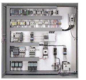
Where this is not possible, the rules above apply. For example:
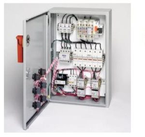
This panel has a 100kA SCCR rating using common components in accordance with UL 508A.
Several definitions for Circuit Types
Several different types of circuits are used in the control panel and are defined below:
Feeder circuit – The conductors and circuitry on the supply side of the branch circuit overcurrent protective device.
Branch circuit – The conductors and components following the last overcurrent protective device protecting the load.
Power circuit – Conductors and components of branch and feeder circuits.
The power circuit can both be connected directly to the supply or via power transformers. Motor- driven loads are mostly classified as power circuits.
Here, respective protective devices are to be used, e.g. circuit breakers according to UL 489.
Control circuit. A circuit that carries the electric signals directing the performance of a controller, and which does not carry the main power circuit. A control circuit is, in most cases, limited to 15 amperes. There are various ways of realizing control circuits:
- Direct tap-off upstream the branch circuit protective device.
- Here, respective protective devices are to be used, e.g. circuit breakers according to UL 489.
- Direct tap-off downstream the branch circuit protective device.
- Here, also so-called supplementary protectors can be used, e. g. miniature circuit breakers according to UL 1077.
- Via control transformers or DC power supply units. Caution: Various protective devices may not be approved for this application.
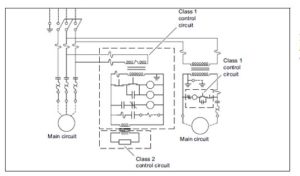
Class 2 control circuit – A control circuit supplied from a source having limited voltage (30 Vrms or less) and current capacity, such as from the secondary of a Class 2 transformer, and rated for use with Class 2 remote-control or signaling circuits (not to be confused with SCCR discussion but definitely <50V and not included in the SCCR discussion). Class 1 control circuit (acc. to UL 508A) – A control circuit on the load side of an overcurrent protective device where the voltage does not exceed 600 volts, and where the power available is not limited, or a control circuit on the load side of a power limiting supply, such as a transformer Class 1 (needs SCCR consideration if control voltage > 50 Vac).
Branch circuit protection – Overcurrent protection with an ampere rating selected to protect the branch circuit. For a motor branch circuit, the overcurrent protection is required for over- currents due to short circuits and faults to ground only.
Field wiring – Conductors to be installed by others to connect the industrial control panel to source(s) of supply, remote control devices, and loads.
An example of a Motor control with class 1 and class 2 control circuits:
Wire Colors
The following are accepted wire colors in a panel in the US or elsewhere:
| Colour | Conductor | Remark |
| Green with or without one or more yellow stripes | Grounding conductor May only be energized in an emergency (not a PEN conductor) | Green/yellow is permitted in accordance with IEC 60204-1. |
| Black | All ungrounded control circuit conductors operating at the supply voltage | |
| Red | All ungrounded AC control circuit cables operating at a voltage less than the supply voltage | |
| Blue (Dark Blue) | Ungrounded DC control circuit cables | |
| Yellow or Orange | Ungrounded control circuit cables which are energized when the main disconnect is in the “off” position. | In IEC 60204-1, orange is used for this purpose. |
| White or gray or three white stripes on conductors, but NOT on green, blue, orange or yellow | Grounded AC current-carrying control circuit conductor regardless of voltage | |
| White with blue stripes | Grounded DC current-carrying conductor | In IEC 60204-1,light blue is used for this purpose. |
| White with orange or yellow stripes | Grounded AC current-carrying conductor that remains energized when main disconnect switch is in the “off” position. |
Leads on tested components, multi-conductor cable, leads used to connect electronic devices, and conductor sizes 20 – 30 AWG are not required to comply with this requirement.
Color Coding for Control and Signaling Devices
General information on START/STOP buttons – UL 508A 66.12
“START – Start operators shall be located above or to the left of the associated stop buttons.
An Industrial Control Panel provided with operator controls shall also be provided with an emergency stop button.
The emergency stop button shall have an actuator that is a mushroom or palm type, and of the self-latching type.
The emergency stop button shall be red with a yellow background.” Color coding:
There are no UL 508A definitions for color coding control and signaling devices. If US specific color coding is however required, reference shall be made to NFPA 79. The following table is taken from NFPA 79:
Color coding for devices according to NFPA 79 Art. 10:
| Colour | Device Function | Typical Function | Example |
| Red | Pushbutton | Emergency stop, stop, off | Emergency stop pushbuttons, Off pushbuttons for one or more motors |
| Indicator light | Danger or alarm, unusual situations; immediate actions shall be taken | ||
| Illuminated pushbutton | Motor overload protection trips due to overload (the color RED for the emergency stop button shall not be dependent on an indicator light). | ||
| Amber | Pushbutton | Intervention in abnormal condition. Warning | Return machine to a safe condition. Bypasses other functions which were previously selected. |
| Indicator light | Abnormal/critical condition, imminent change in condition | Automatic cycle or motor running; some values (pressure, temperature) are approaching a specified limit. Ground fault display. Overload that is permitted for a certain period. | |
| Illuminated pushbutton | Caution, start of process to prevent a dangerous situation from arising | Certain values (pressure, temperature) are approaching the specified values. Pressing the pushbutton bypasses functions which were previously set. | |
| Green | Pushbutton | ON, START | General or machine start. Start of a cycle or a sequence; start of one or more motors; start of auxiliary sequences; excitation of a control circuit. |
| Indicator light | Machine is ready for operation, safe condition. Safe operation | Message reporting a safe condition or approval for subsequent processes. The machine is ready for operation, all conditions are normal, or the cycle is complete and the machine can be restarted. | |
| Illuminated pushbutton | Machine or machine part is ready for operation | ON or START permission, when illuminated, starting of one or more motors for auxiliary functions. | |
| Black | Pushbutton | No special function assigned | May be used for all functions except for the sole function of OFF or STOP |
| White or Transparent | Pushbutton | Functions not mentioned above | Control of functions that are not linked to the operating cycle. |
| Indicator light | Message reporting normal conditions | Normal pressure, temperature | |
| Illuminated pushbutton | Message reporting that an electric circuit has been activated, motion | Excitation of auxiliary functions or electric circuits that are not linked to the operating cycle. | |
| Blue or Gray | Pushbutton | Functions that have not been dealt with by the colors listed above | “Reset” for overload relay |
| Illuminated pushbutton | Functions that have not been dealt with by the colors listed above | “Reset” for overload relay |
With all the information we have above, how does one go about designing a panel? The only answer is to design a panel within the rules of the NEC and the local accommodations given by the electrical inspector for the area. Required is a good general knowledge of the NEC and a relationship with the local inspector(s). Also, a willingness to design panels not as they were designed years ago is necessary. The general move is toward panels with compartments for the
>50V equipment and separate compartments for the <50V equipment. The <50 V side can be trouble-shot as in the past while the newer rules must be accepted when working on the other equipment. Education and certification is a must. The rules as established cannot be ignored.
Minimal Panels or No Panels at All
Based on the complexity of the machine, one machine could have 50-5000 wires of all different colors and characteristics. This requires significant amount of detailed engineering and planning, not only for the I/O, but also for the routing and wiring diagrams for inside the cabinet.
Furthermore, exhaustive debugging follows the electrician’s work of wiring the cabinet. Alternatively, a distributed or machine mount control strategy eliminates several of these steps to simplify overall machine design and build process. At the foundation of the distributed architecture is the network or the fieldbus system that allows for exchange of I/O as messages among networked nodes. Today, almost every machine has adopted some level of distributed controls architecture.
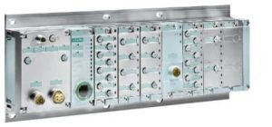
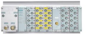
SIMATIC ET 200pro – Compact and multi-functional
Modular and multifunctional distributed I/O system with degree of protection IP65/67:
SIMATIC ET 200pro is an especially small, extremely rugged and high-performance I/O system with IP65/66/67 degree of protection. It comprises Interface Modules to connect with PROFIBUS or PROFINET environment with standard as well as failsafe functionality.
Interface modules are also available with CPU functionality. ET 200pro is characterized by a comprehensive range of modules: power modules, digital and analogue I/O modules, motor starters, frequency converters and an RFID module enable the most flexible response to automation requirements.
Due to its rugged design the ET200 pro can be used when mechanical load is high. Hot swapping of electronics and terminal modules during operation increases plant availability.
CPUs
ET 200pro Interface Modules are offered with CPU functionality in standard or failsafe variants.
CPU 1516pro

The ET 200pro distributed I/O system is being expanded with CPU 1516pro-2 PN and CPU 1516pro F-2 PN. The new CPUs are based on the S7-1500 CPU 1516-3 PN/DP and offer two PROFINET IO communication interfaces.
Standard I/O
Electronic modules
8-channel electronic modules can be combined with the 8 x M12 or 4 x M12 connection
modules. This gives you the choice of single or dual assignment of the M12 sockets.
Digital electronic modules with 4, 8 and 16 channels for 24 V and 4-channel analog electronic modules are available for voltage, current, and resistance thermometers.
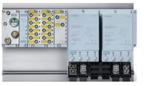
Power modules
Power modules allow load groups to be built up as required by supplementary supply from the load power supply.
Failsafe I/O

The failsafe modules of ET200pro can be used to implement the safety-related application requirements as an integral part of the overall automation.
Motor Starters
Compact, intelligent motor starters
The intelligent ET 200pro motor starters are used for starting and protecting motors and loads of up to 5.5 kW. They are available as Standard and High Feature electromechanical motor starter and High Feature electronic motor-starter versions.
Where a panel is built and eventually installed may change the design:
In the United States, the big three are NFPA (National Fire Protection Association), NEMA (National Electrical Manufacturers Association), and UL (Underwriters Laboratories). Read NFPA 79E – latest edition, NEC – latest edition, and UL508A – latest edition to keep up with panel design and changes to that design.
In Europe, the latest version of IEC 61439-x is to be followed.
Can the two sets of codes be blended? Unfortunately, they cannot be blended although there are some uniformities in the way they approach common problems. You must read and be informed continuously on these codes as they pertain to your application.
Summary
This chapter looks at the construction of a panel and how the construction intersects with the need for safety in the workplace. The need to comply with safety rules over-shadows the other design criteria and has become the determining factor in the design of the control panel. PLCs are still the main element in a panel but their design and the control design in general has been modified to satisfy the need to comply with new safety criteria.
While the student may seem at times disconnected from the real-world aspect of panel design, construction and check-out, he or she might be only months or years away from such an activity. And, many times, a company may take the attitude that safety is not important or not in their best interest. This is never the case and every attempt should be made to encourage and demand that rules be followed. The need for a safety course each year is a requirement of NFPA 70E, 2012. There is no compromise on safety!
If one enters the large corporate enterprise, the decisions may be made by another person who is responsible for a particular portion of the design of a system. However, if the engineer enters the smaller enterprise, then more of the responsibility must be assumed by the new engineer. There is much to be considered and answers may not be immediately apparent. Doing aa design the way they always have been or just following the accepted way may not be the correct path.
Whew! What a lot to consider and get right. No wonder controls engineers are paid a lot. Their responsibilities are only growing with the need for a safe panel that works!
