
18 Planning Tasks
Introduction
As an engineer in controls work, one bumps into problems with timing and task planning on a regular basis. It is never expected but there are times when the problems of computer timing seem to beg to be considered. Usually, the problem is simple and only takes a few minutes of our day. Other times, the problems of tasks being shared and I/O read are a problem worth giving much time to. The lyrics of the song below tell of a poor guy who didn’t plan well and was stuck. Give a listen on the youtube version if led. See why poor Charlie was forever stuck on the MTA.
“The M.T.A.
These are the times that try men’s souls
In the course of our nation’s history the people of Boston have rallied bravely whenever the rights of men have been threatened
Today a new crisis has arisen
The Metropolitan Transit Authority, better known as the M.T.A.
Is attempting to levy a burdensome tax on the population in the form of a subway fare increase Citizens, hear me out, this could happen to you!
Well, let me tell you of the story of a man named Charlie On a tragic and fateful day
He put ten cents in his pocket, kissed his wife and family Went to ride on the MTA
Well, did he ever return?
No he never returned and his fate is still unlearned (what a pity) He may ride forever ‘neath the streets of Boston
He’s the man who never returned
Charlie handed in his dime at the Kendall Square station And he changed for Jamaica Plain
When he got there the conductor told him, “one more nickel” Charlie couldn’t get off of that train!
But did he ever return?
No he never returned and his fate is still unlearned (poor old Charlie) He may ride forever ‘neath the streets of Boston
He’s the man who never returned
Now, all night long Charlie rides through the station Crying, “what will become of me?
How can I afford to see my sister in Chelsea Or my cousin in Roxbury?”
But did he ever return?
No he never returned and his fate is still unlearned (shame and scandal) He may ride forever ‘neath the streets of Boston
He’s the man who never returned
Charlie’s wife goes down to the Scollay Square station Every day at quarter past two
And through the open window she hands Charlie a sandwich As the train comes rumbling through!
But did he ever return?
No he never returned and his fate is still unlearned (he may ride forever) He may ride forever ‘neath the streets of Boston
He’s the man who never returned Pick it Davey
Kinda hurts my fingers
Now, you citizens of Boston, don’t you think it’s a scandal How the people have to pay and pay?
Fight the fare increase, vote for George O’Brian Get poor Charlie off the MTA!
Or else he’ll never return
No he’ll never return and his fate is still unlearned (just like Paul Revere) He may ride forever ‘neath the streets of Boston
He’s the man who never returned He’s the man who never returned He’s the man who never returned Et tu, Charlie?”
Source: LyricFind
Hopefully you will never experience the same fate as Charlie! The song is old but not planning especially regarding computer timing, can lead to some serious catastrophic problems.
An Anecdotal Concerning Timing
One simple problem encountered some years ago had to do with a high-speed counter card. The card was purchased to count the pulses from a pulse output flow meter dealing with flow to a mixer. The flow was to turn off within .1 gallon of total flow from the liquid’s feed line. This was not happening. Every time the ingredient was called, the accuracy was off by .7 or .8 gallon, either plus or minus and never predictable. The time spent on this was of great concern because there was an obvious waste of each batch that had to be scrapped since the liquid was so far out of specification. It was also pointed out that the original flow controller was able to fill the batch to within .05 gallon repeatedly.
Everything looked to be in order. The pulses were coming into the high-speed card accurately and the PLC was scanning the card often enough to read and turn on an output every 10 ms or so. So where was the problem?
Not until a program was written to show the delay between the update from the high-speed counter card to the CPU was the source of the problem revealed. The high-speed counter card was updating but not updating the count to the CPU more than about every .75 seconds, enough to cause the .7 or .8 gallon error. The program, while simple to write, revealed the problem to the engineer. The card was obviously flawed and needed to be replaced. The question became one of was this for this card alone or was the problem with all cards of this design. That question was answered by calling the manufacturer and asking that they put the card on a bench to test for the same problem. When this occurred, it was found that the problem was across the board and the card was essentially not able to control the flow of liquid accurately enough to accurately fill our batch. Another solution would need to be found.
A solution was found that was accurate enough and the problem solved. The manufacturer was embarrassed by this obvious flaw in the design of his I/O card and the problem was only exposed by writing a program to show the delay between updates of the pulsed input to the cpu. He admitted that the card was purchased from a third party (not associated with the manufacturer) and that the design had never been thoroughly checked out (or they would have found the problem themselves).
The solution was to create a frequency divider for the pulsed input from the flow controller and read the inputs into the cpu directly at a slower rate that was able to be updated by the discrete I/O card on the PLC. To slow down the pulse rate was acceptable in this case since the accuracy of the cpu’s scan rate exceeded that needed to turn off the flow valve after a setpoint had been reached. Problem solved!
The following shows a description of the original pulse followed by a frequency divider and then a second frequency divider. It was tempting to build this frequency divider using chips but that is not typically acceptable in a factory environment. A Red Lion counter gave the desired output of a 4:1 count with four input pulses giving a toggled output. This output was slow enough to be read successfully by the digital input on the PLC. The PLC was a Modicon.
Fig. 18-1
Both A-B and Siemens have methods of solving problems such as the one above. Both A-B and Siemens have aggressive methods for dealing with timing issues.
Both use a method to read I/O on an immediate basis rather than from the scan’s own I/O update. If necessary, they allow an instruction to have an immediate read from an input or an immediate write to an output. This is necessary for the processor to guarantee some of the simple high- speed problems of a process. The rest of the chapter outlines some of the more sophisticated methods for problem solving of timing issues and diagnosis of problems when they arise. In Chapter 19, it will be obvious that a scheduled program is needed to help in providing a best possible performance from the PID loops being programmed.
Allen-Bradley – Managing Tasks
The default RSLogix 5000 project provides a single task for all logic. While this is sufficient for many applications, some need more than a single task to perform the requirements of the project.
A Logix5000 controller supports multiple tasks to schedule and prioritize the execution of your programs based on specific criteria. This balances the processing time of the controller.
- The controller executes only one task at one time
- A different task can interrupt a task that is executing and take control
- In any given task, only one program executes at one time A Logix5000 controller supports three types of tasks:
- Continuous
- Periodic
- Event
The continuous task runs in the background. It is the Main program and its sub-programs. It contains most of the code for the program. The periodic task runs on a clock. Programs such as a PID algorithm needs a constant clock execution time to correctly calculate a new output for the PID block. Also included in the PID algorithm is the requirement that the analog values be collected in a timely manner. That is, the analog values cannot be from about a scan ago. They must be refreshed just before needed in the clocked program. An event task runs based on an interrupt. These programs must be guarded in that not too many programs must be created or their frequency must be low in order to be run successfully.
To assign a priority to a task, use these guidelines:
“
| If you want | Then | Notes |
| This task to interrupt another task | Assign a priority number that is less than (higher priority) the priority number of the other task | · A higher priority task interrupts all lower priority tasks
· A higher priority task can interrupt a lower priority task multiple times |
| Another task to interrupt this task | Assign a priority number that is greater than (lower priority) the
priority number of the other task |
|
| This task to share controller time with another task | Assign the same priority number to both tasks | The controller switches back and forth between each task and
executes each one for 1 ms |
“
Leave enough time for unscheduled communication. Unscheduled communication occurs only when a periodic or event task is not running. If you use multiple tasks, make sure that the scan times and execution intervals leave enough time for unscheduled communication. Use these methods to plan enough unscheduled communication time.
- Verify that the execution time of a highest priority task is significantly less than its specified period.
- Verify that the total execution time of all tasks is significantly less than the period of the lowest priority tasks.
Manually check for overlaps using the following steps:
Fig. 18-2
Module Input Data State Change Trigger:
To trigger an event task based on data from an input module, use the module Input Data State Change trigger shown below:
Fig. 18-3
Some A-B I/O has the ability to send the I/O status to multiple processors. This is referred to as an I/O Module Trigger to an event Task. We will not discuss this topic further here since the I/O is not present in the lab and we do not need this capability to process any information. However, do remember that the more sophisticated processors have this capability and it should be considered when planning a project.
Siemens
Siemens, like Allen-Bradley, has a sequence of events that occur when the processor starts up and then services the I/O and solves logic during the scan of the processor. It is roughly described in the following diagram:
Fig. 18-4
Operating modes of the CPU
The CPU has three modes of operation: STOP mode, STARTUP mode, and RUN mode.
“The system guarantees that the scan cycle will be completed in a time period called the maximum cycle time; otherwise a time error event is generated.
- Each scan cycle begins by retrieving the current values of the digital and analog outputs from the process image and then writing them to the physical outputs of the CPU, SB, and SM modules configured for automatic I/O update (default configuration). When a physical output is accessed by an instruction, both the output process image and the physical output itself are updated.
- The scan cycle continues by reading the current values of the digital and analog inputs from the CPU, SB, and SMs configured for automatic I/O update (default configuration), and then writing these values to the process image. When a physical input is accessed by an instruction, the value of the physical input is accessed by the instruction, but the input process image is not updated.
- After reading the inputs, the user program is executed from the first instruction through the end instruction. This includes all the program cycle OBs plus all their associated FCs and FBs. The program cycle OBs are executed in order according to the OB number with the lowest OB number executing first.”
Interrupt latency
The interrupt event latency (the time from notification of the CPU that an event has occurred until the CPU begins execution of the first instruction in the OB that services the event) is approximately 175 μsec, provided that a program cycle OB is the only event service routine active at the time of the interrupt event.
Understanding time error events
The occurrence of any of several different time error conditions results in a time error event. The following time errors are supported:
- Maximum cycle time exceeded
- Requested OB cannot be started
- Queue overflow occurred
The maximum cycle time exceeded condition results if the program cycle does not complete within the specified maximum scan cycle time. See the section on “Monitoring the cycle time in the S7-1200 System Manual” (Page 80) for more information regarding the maximum cycle time condition, how to configure the maximum scan cycle time, and how to reset the cycle timer.
The requested OB cannot be started condition results if an OB is requested by a cyclic interrupt, a time-delay interrupt, or a time-of-day interrupt, but the requested OB is already being executed. The queue overflow occurred condition results if the interrupts are occurring faster than they can be processed. The number of pending (queued) events is limited using a different queue for each event type. If an event occurs when the corresponding queue is full, a time error event is generated. All time error events trigger the execution of OB 80 if it exists. If an OB 80 is not included in the user program, then the device configuration of the CPU determines the CPU reaction to the time error:
- The default configuration for time errors, such as starting a second cyclic interrupt before the CPU has finished the execution of the first, is for the CPU to stay in RUN.
- The default configuration for exceeding the maximum time is for the CPU to change to STOP.
Recording of measured values with the trace function:
The trace and logic analyzer function can be called in the device folder in the project navigator under the name “Traces”. You record device tags and evaluate the recordings with the trace and logic analyzer function. Tags are for example drive parameters or system and user tags of a CPU. The maximum recording duration is limited by the memory size. How much memory is available for the recording depends on the hardware used.
Fig. 18-5
While all this may seem rather bothersome, the exercise to make sure the scan has enough time and there is sufficient memory to accomplish the task is very important. It is too late if the project is nearing start-up to find out these problems. Then they are a catastrophe.
Timing issues can definitely stop a good project in its tracks. There are a number of software issues that can be hard to conquer but timing issues are one of the worst.
A Timed Interrupt Program
The following program is an example of a timed interrupt program saved in OB30 (Siemens). This program is found in Chapter 19 since the program uses the PID block. However, the use of a timed interrupt program is essential for proper execution of the program. Back in Chapter 10, a timed interrupt program was used to count calories. What was needed was a .1 second or .01 second interrupt that calculated the number of calories in the last 100 or 10 msec and added them to those already expended. The result was a graph of calories that grew with time and the load on the bike measured in watts from the light bulbs and by the ache in the legs.
The following program has a problem in that the program could be executed in any time range from .1 second to .001 second. It is primarily determined by the accuracy of the speed which is a function of the number of pulses received in the time period.
First, 10 msec was picked and found that the maximum number of pulses in the time period was 12, not enough to accurately control the PID algorithm. Who wants a speed control that can only be controlled to 1 part in 12? That is not a good outcome. However, if one extends the time period, we lose the ability to make quick changes in the function. The function is the control of a simple dc motor with feedback control through an encoder. The encoder was simply not accurate enough to allow an increase in the update speed of the program. So, for 100 msec time period, we would get about 120 pulses for an extremely low accuracy encoder.
The following figure shows the configuration of the system including the cyclic interrupt (OB30).
Fig. 18-6
The following figure describes the input waveform configuration. The input must be allowed to be read very fast – in this case, 20 microseconds.
Fig. 18-7
The following describes the high-speed counter configuration. The input is HSC_1. Wiring terminal and address is found in the next figure:
Fig. 18-8
The input to pulse A is wired to I4.1:
Fig. 18-9
The input is addressed in the program as ID1000. This address appears in the program statement in the logic below:
Fig. 18-10
The following program reads the input and determines the number of pulses since the last scan. In this case, the pulse count is the count in the last 100 msec.
Fig. 18-11
A Problem Using Timed Interrupt ProgrammingFor the process below, the roll conveyor carries boxes from left to right. If a box is too close to the one before it, the spacing bar comes up (arrow) to hold it back until a constant spacing is achieved. If a box is spaced in excess of the minimum, the box is allowed to pass on with no blocking. Write a program in ladder logic to control the blocking bar based on the photo-eye and an input from a pulse tachometer. Assume the pulse tach is a dint word with a constantly increasing number of pulses each time read.
Fig. 18-12
This problem uses the pulse counter described in the program above to find the movement of the conveyor and the boxes per unit of time. The problem should be run about every 10 msec since the movement of the boxes probably will be able to move less than ¼ inch in that time and the control of the spacing boxes would be adequate based on this ¼ inch requirement.
The photo-eye would see the leading edge and the trailing edge of the previous box can be tracked. When the box’s leading edge moves to the blocking bar, a decision is made whether to activate it. If activated, then the tracking continues until the distance from the last trailing edge is exceeded and the blocking bar is deactivated or blocked.
This problem is assigned in the Problems section.
Another Anecdotal:
In 1972, this author was placed on a project team that was responsible for the automatic tracking of glass on a cutting machine for a major glass manufacturer. The team leader was experienced and confident the project would proceed well. The other team member was experienced as well. I was the newbie.
The team leader in early 1973 quit. And the other team member, while willing to help, was relegated to the bench due to competition between plants. The new plant was purported to be non-union and the plant that he worked for was union. Thus, I was the last one standing.
The project was to track glass on 66 sections of conveyor. The prior job for which the team leader and other member had worked had only 6. They used interrupts for each pulse that came in to the computer which represented each 1.5 inches of travel of the conveyor. I looked at the interrupt light for this interrupt category and it was on pretty bright. What would happen if the number of interrupts increased by a factor of 10? I had no idea. And I was alone. So what did I do?
I changed the program to a scanned program that would execute each 8 msec. In this format, multiple pulse inputs would possibly change in each execution of the program but there would be only one interrupt each 8 msec. This change, while not monumental, was significant. I just implemented it. I did not ask. I just went ahead.
Later, my boss was discussing something along the lines of the portion of the program in question and I happened to mention that I had changed it to a scanned program. I thought I would be fired from the look on his face. I wasn’t. He reviewed with me the change and went along with it.
The program worked. It collected data from all 66 conveyors and tracked, not at 1.5 inch accuracy but at .75 inch accuracy since I executed on both the rising and trailing edge of the signal. So, it was twice as accurate. The light was also not as intense as the light on the prior program. It seemed to run ‘cooler’.
I don’t know if this change ‘saved’ the project. I don’t care. I just know that it worked the way I programmed it.
And, I became a firm believer in the expression “it is better to ask for forgiveness than to ask for permission.” You see, I doubt if my boss would have gone along with a ‘theory’ that the program would fall apart once moved to 66 conveyors using interrupts. It would have been hard to prove one way or the other and he would have reverted to the way it had previously been done. I was responsible for the project and was conservative in the use of time. Neither could prove absolutely the right way to go. It worked the new way and, in the process, saved money on the future purchases of computers used in the work in that the original computer cost about $100K and the ones that could now be purchased would cost only about $30K, a savings of $70K. Not bad.
Finally
The following table is found in the S7-1200 Programmable Controller System Manual. The table gives execution times for instructions in the PLC. It will be used in a problem at the end of the chapter. It is useful to calculate the execution time for your programs. Use it!
The following pages are from the Siemens Text:
Programming Guideline for S7-1200/1500 Entry ID: 81318674, V1.6, 12/2018They summarize changes and upgrades to the Siemens Portal Language from Version 14 – TIA and later:
LINK TEXT HERE
Summary
From the beginning of this chapter, the discussion has been one of planning to not fail by running out of something. In the case of Charlie and the MTA, it was a nickel that was needed. During the remainder of the chapter, the quantity is time. The plan should include enough time to guarantee execution of all programs without failing. The conservative planner usually allows extra time and he is more successful in his implementation of the overall system. Don’t run out of CPU time!
Problems
- For each example, list whether the task would be best programmed as a continuous, periodic or event (interrupt driven) task.
- Fill a tank to its maximum level and then open a drain valve
- Read the thickness of a paper roll every 20 ms
- A gluing station must adjust the amount of glue it applies to compensate for changes in the speed of the axis. After the motion planner executes, check the command speed of an axis and vary the amount of glue, if needed.
- Your system must check the position of a field arm each 0.1 s and calculate the average rate of change in its position. This is used to determine braking pressure
- In a production line, if any of the programs detect an unsafe condition the entire line must shut down. The shutdown procedure is the same regardless of the unsafe condition
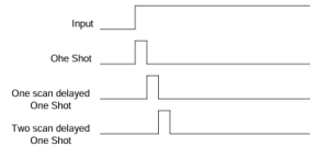
- For the following figure, provide logic for each one-shot. Identify in your program each signal labeled below. You may use either Siemens or A-B one-shot logic or you may create the logic entirely without one-shot instructions:
- Write the program that would accomplish the task described in the chapter that was solved by using a frequency divider (prove that the update between the card and the CPU was happening only about every ¾ second)
- Pick a commercial wheel with toothed gears and a proximity switch wired to a PLC input. Describe analytically how fast the wheel is allowed to turn in order for the program in your PLC to be guaranteed to not miss any pulses without using a high-speed pulse counter input.
- For the process below, the roll conveyor carries boxes from left to right. If a box is too close to the one before it, the spacing bar comes up (arrow) to hold it back until a constant spacing is achieved. If a box is spaced in excess of the minimum, the box is allowed to pass on with no blocking. Write a program in ladder logic to control the blocking bar based on the photo- eye and an input from a pulse tachometer. Assume the pulse tach is a dint word with a constantly increasing number of pulses each time read.

- Use a program previously written and using the table in the ‘Finally’ section of the chapter to calculate the execution time of the program. Do you think you will ever do this in the real world? If you do not, think again!
This work is licensed under a Creative Commons Attribution 4.0 International License.
