
Leica CM1520 Cryostat
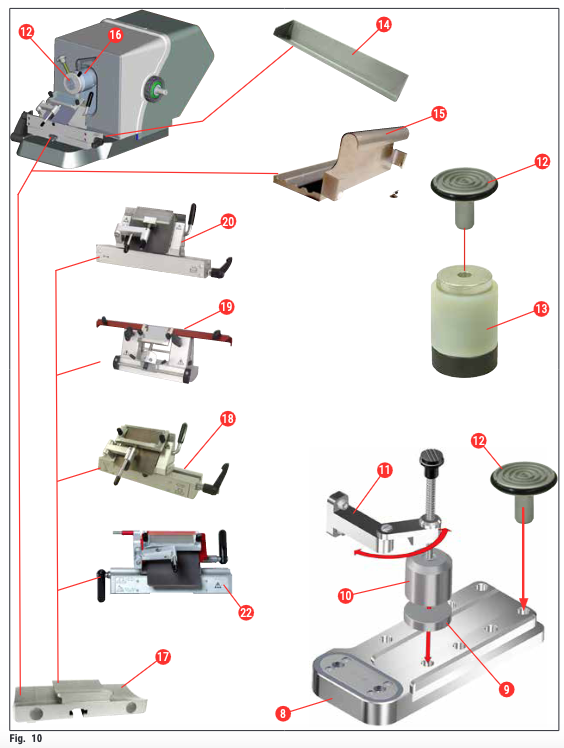
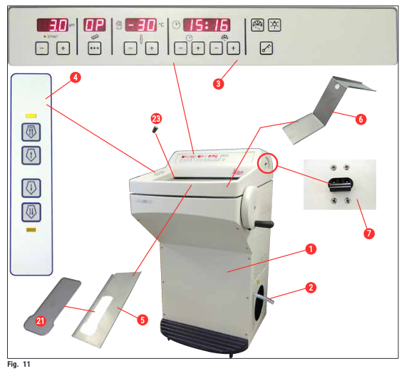
- Leica CM1520
- Drain hose
- Control panel 1
- Control panel 2
- Storage shelf, left
- Storage shelf, right
- Automatic fuse and ON/OFF switch
- Quick-freeze shelf
- Parking station (optional)
- Stationary heat extractor (optional)
- Heat extractor holder (optional)
- Specimen disc
- Thermal block (optional)
- Section waste tray
- Brush shelf
- Orientable specimen head
- Blade/knife holder base (optional)
- Blade holder CE (optional)
- Knife holder CN (optional)
- Blade holder CE-TC (optional)
- Freeze shelf cover
- Premium blade holder
- Rubber plug
Operating the Instrument
Control panel
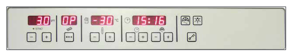
Function keys
 Lamp button.
ON/OFF switch for cryochamber illumination

Manual defrost button. For switching the manual defrost on and off

Key button. To lock and unlock the control panel to protect the entered parameters from unintended modifications. Enable/disable the lock by pressing and holding for 5 seconds.
Configuring the desired values
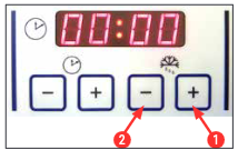
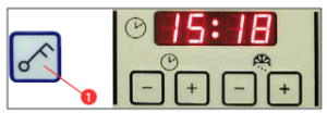
Setting the time
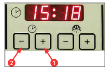
Use the function button labeled with a clock symbol to set the time of day.
- Set the current time using the Plus (→ “Fig. 15-1”) and Minus (→ “Fig. 15-2”) buttons.
- Pressing and holding the Plus or Minus button continuously increases or decreases the time (auto-repeat function)
Setting the automatic defrost time (cryochamber)
The automatic defrost cycle takes place once every 24 hours.
- Briefly touch the Plus (→ “Fig. 16-1”) or Minus (→ “Fig. 16-2”) button to display the beginning of the defrost time that is currently set. The two LEDs between the display of hours and minutes flash at the same time.
- To change the beginning of the defrost time in 15-minute increments, touch or press and hold the Plus or Minus button. The defrost duration is 12 minutes.
Programming the temperature of the cryochamber
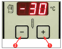
The temperature of the cryochamber is set and indicated on the panel marked with the cryostat symbol.
- The actual temperature is the standard indication. Briefly touch the Plus (→ “Fig. 17-1”) or Minus (→ “Fig. 17-2”) button to display the target temperature.
- You can now set the desired value using these buttons. Pressing and holding the Plus or Minus button continuously increases or decreases the cryochamber temperature.
- 5 seconds after finishing the programming the current value will be displayed again
Manual defrosting of the quick freeze shelf
Warning
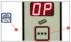
- You can activate the manual defrost of the quick freeze shelf by pressing the key (→ “Fig. 18-1”) (continuous tone sounds), followed immediately by the key (→ “Fig. 18-2”) (continuous tone stops). The display flashes during the defrosting.
- To shut off the manual defrost early, press the (→ “Fig. 18-1”) key, followed immediately by the (→ “Fig. 18-2”) key. The quick freeze shelf can become hot during the defrosting process. The defrost duration is 12 minutes.
Note
Manual defrosting of the cryochamber
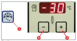
- You can activate manual defrosting of the cryochamber by pressing the key (→ “Fig. 19-1”) (continuous tone sounds), followed immediately by the key (→ “Fig. 19-2”) in the cryochamber temperature selection field (continuous tone stops). The display flashes during the defrosting (duration 12 min.).
- To shut off the manual defrost early, press the (→ “Fig. 19-1”) key, followed immediately by the (→ “Fig. 19-3”) key in the cryochamber temperature selection field.
Setting the section thickness
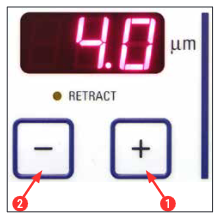
Adjust the section thickness in a range from 2 – 60 μm using the Plus (→ “Fig. 20-1”) and Minus (→ “Fig. 20-2”) push buttons in the upper control panel (→ “Fig. 20”):
2 μm – 5 μm in 0.5 μm increments,
5 μm – 20 μm in 1 μm increments,
20 μm – 60 μm in 5 μm increments.
The preselected section thickness appears in the display above the keys.
- Start trimming at approx. 20 μm.
- Decrease the section thickness continuously until the required thickness is reached.
- After changing the section thickness, discard the first two or three sections.
- For sectioning, turn the handwheel at a constant speed
Display lock
After the display is locked using the Key button (→ “Fig. 21-1”) (press and hold for 5 sec.), set values can NO LONGER be changed.
- To unlock the display, press and hold the Key button (→ “Fig. 21-1”) again for 5 seconds.
When the display is locked, the LEDs between the hour and the minute display on the time panel are turned off (→ “Fig. 21”).
Control panel 2 – Electric coarse feed
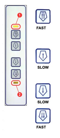
Moving the specimen away from the knife
- Fast return to the rear end position starts.
The LED (→ “Fig. 22-1”) flashes while the specimen head is in motion.
-
- The LED lights up when the rear end position has been reached (→ “Fig. 22-1”).
- The return movement can be stopped by pressing one of the coarse feed buttons.
- Slow return to the rear end position starts.
- The motion continues as long as the button is held.
Advancing the specimen toward the knife
- Fast or slow feed toward the knife starts.The LED (→ “Fig. 22-2”) starts flashing as long as the specimen head is in motion.
The LED lights up when the forward end position has been reached (→ “Fig. 22-2”).
To feed the specimen, press and hold the appropriate Slow or Rapid button.
Daily Use of the Instrument
The sectioning process
Preparation
- Install all necessary parts, whether standard or optional (e.g. panels, waste and brush tray and
the selected knife or blade holder). Make sure that they are mounted and cooled. - Set the chamber temperature according to the tissue type to be sectioned (→ P. 56 – 7.5 Temperature selection chart (in minus °C)).
- Freeze specimen onto a specimen disc (→ P. 38 – 7.3 Specimen discs) and mount it into the specimen head (→ P. 38 – 7.3.1 Inserting the specimen discs into the specimen head).
- Make sure that the knife or blade is inserted in the knife or blade holder, see (→ P. 42 – 7.4.4 Blade holder CE) or (→ P. 48 – 7.4.6 Knife holder CN).
- Orient the specimen (→ P. 38 – 7.3.2 Specimen orientation).
- If necessary, adjust the clearance angle (→ P. 40 – 7.4.2 Clearance angle adjustment).
Sectioning
- Select trimming thickness.
- Adjust anti-roll device (→ P. 46 – Adjusting the anti-roll guide system).
- Trim using the handwheel (→ P. 55 – Trimming the specimen).
- Select section thickness (→ P. 34 – 6.2.6 Setting the section thickness).
- Carry out sectioning using the hand wheel, discard the first 2-3 sections.
- Pick up the sections either by transferring it onto a cold slide using a cold brush or a warm slide.
Ending the sectioning process
- Remove knife/blade out of the knife/blade holder
Warning
- Remove the specimen from the cryostat e.g. fix it for later paraffin embedding.
- Remove section waste using a cold brush.
Specimen freezing
- Select the sectioning temperature (cryochamber temperature) according to the tissue type to be sectioned (→ P. 56 – 7.5 Temperature selection chart (in minus °C)).
Quick-freeze shelf
The cryochamber is equipped with a quick freeze shelf (→ “Fig. 23-5”) on which up to 10 specimen
stages with specimens can be stored.
The temperature of the quick freeze shelf is always lower than the cryochamber temperature.
1. Cut the specimen roughly to size.
2. Apply a sufficient amount of cryocompound to a specimen disc that is at room temperature or
pre-cooled.
3. Place the specimen on the disc and orient it.
4. Place the specimen disc in one of the holes of the quick freeze shelf and freeze the specimen at
low temperature.
5. Once the specimen is frozen, insert the specimen disc (→ “Fig. 23-3”) with the specimen into
the specimen head (→ “Fig. 23-2”) and start sectioning.
Note
Daily Use of the Instrument
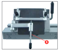
Adjusting the anti-roll guide system
You can adjust the height of the anti-roll guide system using the knurled nut (→ “Fig. 38-8”):
- If you turn the nut counterclockwise, the anti-roll guide system moves toward the blade.
- If you turn the nut clockwise, the anti-roll guide system moves away from the blade.
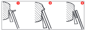
If the anti-roll guide system is in the wrong position relative to the blade, the following problems will result:
» The section rolls over the glass insert of the anti-roll guide system (→ “Fig. 39-1”).
Error: Glass insert not high enough.
✓ Remedy: Turn the knurled nut counterclockwise until the section is pushed between the blade and anti-roll guide as shown in (→ “Fig. 39-3”).
» Section are compressed and block hits the glass insert (→ “Fig. 39-2”) after sectioning.
Error: Anti-roll guide system is set too high.
✓Remedy: Turn the knurled nut clockwise until the section is pushed between the blade and anti-roll guide as shown in (→ “Fig. 39-3”).
Reproduced from pages: 28 – 29, 31 – 37, 46 of the Leica BioSysytems instructions for CM1520 Cryostat.[1]
- https://www.leicabiosystems.com/sites/default/files/media_product-download/2022-01/Leica_CM1520_IFU_2v4O_en.pdf ↵