
6.8 Venting Grease Traps
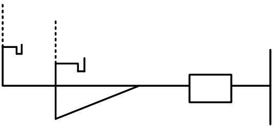
Older model grease traps required a Flow Control Device (as shown below) to restrict the volume of water that would flow through the grease interceptor. These fittings have a ½” vent which prevented the grease trap from air locking. On the drawing below just above the air vent, the orifice was installed. The larger the orifice diameter the greater the GPM. If the orifice became plugged the L shaped handle is slid in and cleared the orifice opening.
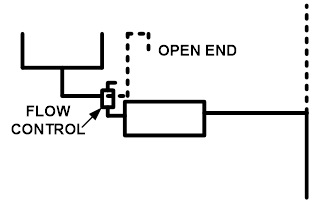
Some manufacturers use an orifice plate located close to the inlet to control the flow and some manufacturers use the grease interceptor itself to control the flow rate. The grease trap may serve as the trap for the fixture as long as the fixture outlet does not exceed 1200 mm and has a trap seal of at least 38 mm. If the grease interceptor uses a flow control valve the ½” air vent must be piped up to flood level rim and then return using 2 – 90 degree elbows. The end may be left opened in the room because sewer gas would not be a problem since the interceptor is a trap.
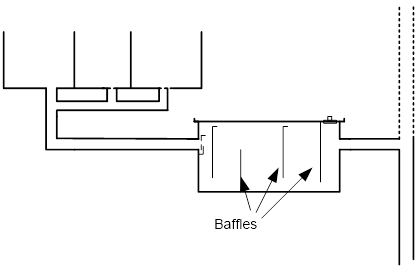
Some manufacturers use baffle plates installed in the interceptor.
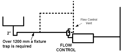
In the drawing below the interceptor cannot act as the trap for the fixture because the fixture outlet pipe would be longer than 1200 mm. The fixture must be trapped and vented. Note that the 1/2” flow control vent must be tied into the venting system to prevent sewer gas from exiting the vent.
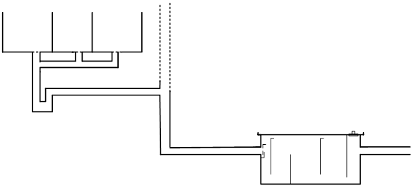
In the drawing below the two fixtures are Individually Vented. Note that this interceptor doesn’t have a flow control valve which indicates that internal baffles are used.
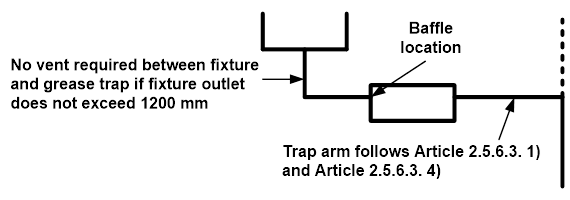
In the diagram below the interceptor is acting as the trap and must be vented. The maximum length of the fixture out is 1200 mm.
In the diagram below the interceptor is more than 1200 mm away from the fixture. The fixture now must be trapped and vented. Its also recommended that fixtures served by grease interceptors have a drain down time of 2-3 minutes.
In the diagram below both fixtures are required to drain into the grease interceptor both fixtures require traps and vents.
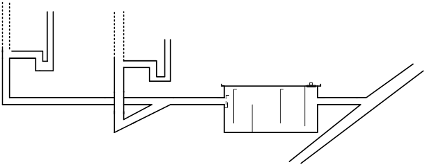
In the diagram below the triple compartment sink is required to drain into the grease interceptor, If the other fixture was for example a hand washing sink then it would not be required to drain into the interceptor. Both fixtures require traps and vents.
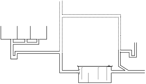
Image Credits
- Zurn. (n.d.). Z1108 Flow Control Device. https://www.zurn.com/products/building-drainage/grease-oil-sediment-separation/options/z1108