
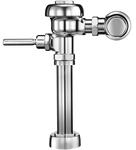
10. Flushometer
Advantages of the flush valve
Rapid Cycle
The flush valve cleanses its companion fixtures and stands ready for reuse in a matter of seconds. In public installations where rest periods or intermissions cause peak traffic, this quick action makes the specification of flush valves mandatory.
Efficient Flushing
Since the flush valve operates on direct supply line pressure, flushing action is forceful and complete. The drawn-out, lazy flush is eliminated, and danger of bowl stoppage is sharply reduced.
Low Initial Cost
The cost of piping material necessary for the supply of flush valves tends to approach and equal piping costs for other methods of flushing as the number of flush valves on a line increases.
Water Economy
The flush valve consumes no more water per flush than any other device. In addition, the flush valve is unique in that it may be adjusted to the companion fixture to supply just enough water for the satisfactory flush.
Ease of Operation
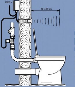
Flush valves may be actuated in a variety of ways depending upon the requirements of the installation. They may be supplied with handles, push buttons, foot pedals, or electrical actuating devices.
Quiet Action
Flush valves of today are available with quiet flushing equipment to reduce flushing noises. When coupled with fixtures specifically designed for quiet operation, the ultimate in noiselessness may be achieved.
ROUGH USAGE INSTALLATIONS
Where vandalism may be a factor, the flush valve can be concealed out of the way of harm.
There are two main types of flush valves, they are:
- Diaphragm
- Piston
They can be broken down into two different classifications, they are:
- Hold Open
- Non Hold Open
The hold open type valve flushes continuously when handle is held in the open position, as the handle is released the flush will stop. By misuse this type of valve can waste water.
The non hold open type valve has a telescopic relief valve stem. This type of valve is commonly installed in public washrooms, because they conserve water.
Since two pressure chambers are used in a flush valve, the two different types simply refer to the method used to separate the two pressure chambers. The diaphragm type was in use first and the piston type was developed because of frequent ruptured diaphragms, however, this has been overcome by using synthetic diaphragm materials.
(Neoprene, etc.) The two types are equally reliable, some manufacturers are specializing in one type or the other. The plumber’s selection is usually limited to the type specified by the mechanical engineer.
A flush valve installation differs from a flush tank installation in that water flows under line pressure into the fixture. While in a flush tank the water is first accumulated in the tank and then flows into the fixture by gravity.
A flush valve requires a minimum pressure of 10 PSI (25 PSI for blowout type fixtures). With a flush tank the pressure of water entering the fixture equals approximately 1/2 PSI.
NON-HOLD OPEN VERSUS HOLD-OPEN NON-HOLD OPEN
In addition to the fact that there are basically two types of flush valves (Diaphragm type and Piston type), flush valves are found to be of the non-hold-open or hold-open type. The two valves are so constructed that when the valve is flushed, the bottom of the relief valve stem is carried (by the diaphragm or piston) above the plunger. If the handle is held down so that the plunger in turn is held in the extended position, then when the valve is closing, the relief valve stem comes down on top of the handle plunger and telescopes within itself, permitting the working parts to return to the main seat, shutting off the valve upon completion of its normal cycle.
In other words, non-hold open valves will go through its complete cycle and shut off regardless of whether the handle is held or released.
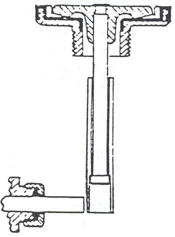
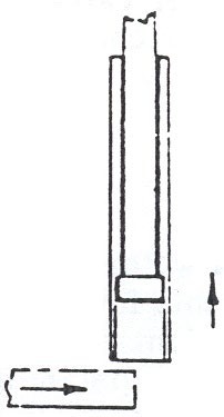
The Principle of Non-Hold Open
 |
 |
 |
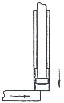 |
- Flush Valve in closed position.
- The thrust of handle plunger tilts the Relief Valve and opens the upper chamber.
- After the diagram lifts the Relief Valve stem is carried above the Handle Plunger.
- Relief Valve stem showing telescoping gland collapsed on top of extended Handle Plunger permitting the diagram to return to the main seat while the valve is closing.
HOLD OPEN
Hold open flush valves have longer, solid Relief Valve stems so that the handle plunger and the stem are constantly engaged. Thus the valve can be held open to waste water. These, therefore, are known as hold-open Flush Valves.
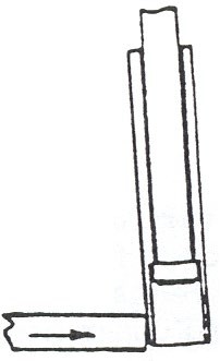
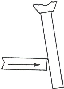
The principle of hold-open
 |
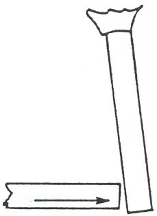 |
- Flush Valve in closed position.
- The thrust of handle plunger tilts the Relief Valve and opens the upper chamber.
- After the diagram lifts the Relief Valve stem is still in contact with the Handle Plunger.
Operation of a Diaphragm Type Flush Valve
Design
All flush valves regardless of type employ an upper and lower chamber to allow a metered amount of water to pass through the valve with each flush. In the method employed to separate these two chambers lies the essence of the diaphragm type flush valve. Instead of a negative slip seal separation the diaphragm type valve employs a
water tight diaphragm positively locked into position around its perimeter. A diaphragm valve will deliver exactly the same measured quantity of water with each flush until the diaphragm requires replacement. Such consistency of delivery is a hallmark of diaphragm type valves. The one hundred thousandth flush should be identical to the first flush.
Construction
The internal operating assembly of a diaphragm type valve is comprised of six simple moving parts. The number of potential breakdown points is minimal. Shown below is the operation of a diaphragm flush valve as it goes through a complete cycle.
Timing of the flushing cycle
On-the-job setting of the flushing cycle is quickly and easily accomplished with the external adjustment feature. A twist of a screwdriver on the regulating screw (h) shortens or lengthens the upward travel of the diaphragm assembly before it is halted by the lower end of the regulating screw. The length of the flush cycle is proportional to the vertical rise of the diaphragm assembly. The setting is permanent and utilizes no watch like moving parts subject to wear or misalignment.
This easy external adjustment permits each valve to be accurately tailored to its companion fixture, reducing unnecessary water wastage.
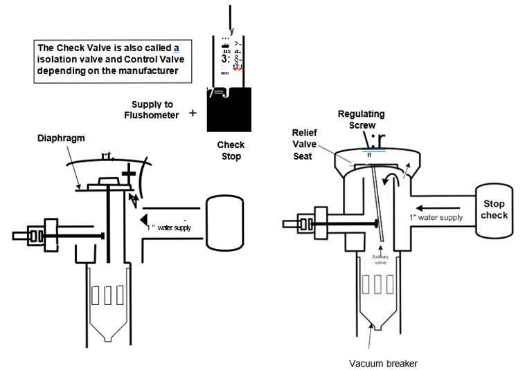
Image Credits
- Sloan Valve Company. (n.d.). Sloan 186-0.5 DFB Urinal 0.5 GPF Flushometer. https://www.sloanplumbingparts.com/sloan-186-0-5-dfb-urinal-flushometer
- Commercial Washrooms. (2012). Delabie Individual Toilet. https://www.commercialwashroomsltd.co.uk/