
7. Oil Interceptors
Note
You are required to complete the following Quiz in this section and fax or email it back to your instructor for correction.
Please ensure you have faxed or emailed the required quiz to your instructor before making arrangements to write your final exam since you will not have access to your final exam until your instructor verifies your faxed drawings.
Purpose of interceptors
Collect oil, gasoline or other explosive liquids and prevent their entry into a drainage system.
Establishments likely to be affected
- Auto repair centres
- Plane hangers
- Machine shops
- Refineries
- Dry cleaning plants
- Paint manufacturing plants
Hazards created by the discharge of explosive liquids
- Fire
- Explosions
- Pollution
- Sewage treatment plant problems
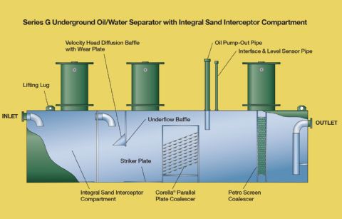
Principal of operation
Specific gravity is the operating principle for interceptors. Oil, gasoline and benzene and other similar solvents are less dense than water. If a mixture of oil, gas or other similar substance and water are held in a container, it will tend to separate. The water being heavier will sink to the bottom of the container and the oil will float to the top.
The interceptor provides the container through which the discharge must pass. The flow must be slowed down (control fitting) to allow heavy sand and dirt to settle to the bottom and oil to separate from the water and rise to the top.
The efficient and proper operations of the separator depend on the flow upstream of the separator being as smooth and gentle as possible, so as to preserve the average droplet size as large as possible. For this reason, it is necessary to install an inlet pipe of the same diameter as the inlet and extending straight, without elbows or other fittings at least ten pipe diameters upstream of the separator. Inlet piping should be as smooth as possible to avoid turbulence caused by pipe roughness.
SERVICING
Oil interceptors must be cleaned out at regular intervals. The waste oil must pumped out into supplied containers that will be disposed of in an approved method.
Venting requirements
2.5.5.2.
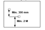
Two vents each having a minimum diameter of 1 1/4” or one size smaller than the largest drain entering the interceptor and must be connected to the oil interceptor at opposite ends. The two vents must terminate outside the building not less than 2 meters above grade, and one higher than the other by 300 mm to create air flow through the interceptor by convection. The flow of air evacuates the gases to the atmosphere minimizing the danger of explosion. Vent pipes cannot be connected to any other vent pipe in the building or to each other.
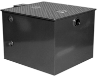
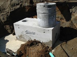
types of oil interceptors
 |
 |
Code Book[1]
Division A
1.4.1.2. Definitions
Interceptor means a receptacle that is installed to prevent oil, grease, sand or other materials from passing into a drainage system.
Division B
2.2.3.2. Interceptors
- ) Every interceptor shall be designed so that it can be readily cleaned.
2.4.4.3. Grease Interceptors
- Where the discharge from a fixture may contain oil or gasoline, an oil interceptor shall be installed. (See Article 2.2.5.2. for venting requirements for oil interceptor.)
- Where a fixture discharges sand, grit or similar materials, an interceptor designed for the purpose of trapping such discharges shall be installed.
- Every interceptor shall have sufficient capacity to perform the service for which it is provided.
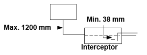
2.4.5.1. Traps for Sanitary Drainage Systems
- An interceptor with an effective water seal of not less than 38 mm may serve as a trap. (See Appendix A.)
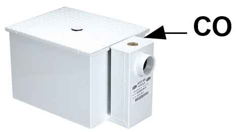
2.4.7.1. 8) A cleanout shall be provided to permit the cleaning of the piping downstream of an interceptor. Manufactured interceptors usually have the CO located above the outlet.
Venting
All Zurn oil interceptors must be vented to atmosphere and are furnished with vent connections of 1-1/4″ or 1-1/2″ IPS on both the right- and left-hand side of the interceptor as specified to suit the installation. If necessary, the vent connection can be changed from one side to the other at the time of installation.
The vent connections are located above the adjustable gravity oil draw-off standpipe and in the intercepting chamber on the upstream side of the trap seal. Thus, the volatile gases rising from the intercepted substances are carried from the interceptor to the atmosphere.
2.5.5.2. Venting of Oil Interceptors[2]
(See Appendix A) (Also see Article 4.3.5.2. of Division B of the NFC.)
- Every oil interceptor shall be provided with 2 vent pipes that
- connect to the interceptor at opposite ends,
- extend independently to outside air, and terminate not less than 2 m above ground and at elevations differing by at least 300 mm.
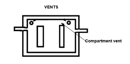
- Adjacent compartments within every oil interceptor shall be connected to each other by a vent opening.
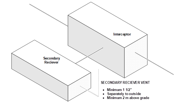
- Where a secondary receiver for oil is installed in conjunction with an oil interceptor, it shall be vented in accordance with the manufacturer’s recommendations, and the vent pipe shall
- in no case be less than 1 1/2 inches in size,
- extend independently to outside air, and
- terminate not less than 2 m above ground.
- The vent pipes referred to in Sentence 1) are permitted to be one size smaller than the largest connected drainage pipe but not less than 1 1/4 inches in size, or can be sized in accordance with the manufacturer’s recommendations.
- Every vent pipe that serves an oil or grease interceptor and is located outside a building shall be not less than 3 inches in size in areas where it may be subject to frost closure.
2.5.6.5. 2) The upper end of every vent pipe that is terminated in outside air, other than a vent pipe that serves an oil interceptor or a fresh air inlet, shall be extended above the roof.
Maintenance
Periodic checks of the oil level in the oil storage compartment is recommended. The accumulated oil in the storage compartment should be pumped out before the oil level has risen to the gate plate height. As these periodic checks are made, a general inspection of the interceptor, plumbing connections and gasketing should be made. Any required maintenance needed should be performed at this time.
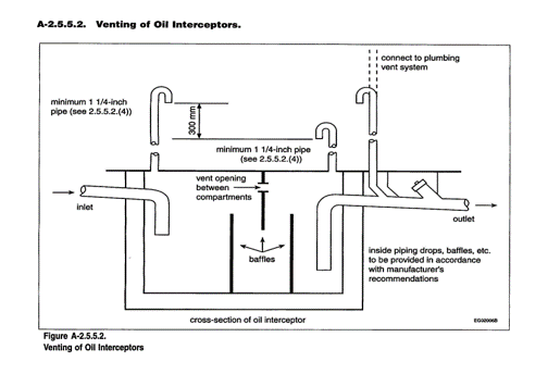
Image Credits
- Highland tank, (n.d.). Highland Tank Oil/Water Separators. https://www.highlandtank.com/wp-content/uploads/2019/12/TechNews_Yellow_MIA_Airport.pdf
- Large Capacity Oil Interceptor. Credit: Zurn. (n.d.). Z1188. https://www.zurn.com/products/building-drainage/grease-oil-sediment-separation/oil-solids-interceptor/z1188Oil Interceptors.
- Langley Concrete. (n.d.). Oil Interceptors. https://www.langleyconcretegroup.com/products/oil-interceptors
- Credit: Langley Concrete Group. (n.d.). Oil Interceptors. https://www.langleyconcretegroup.com/
- Zurn. (2013). Grease interceptors. https://www.zurn.com/products/building-drainage/grease-oil-sediment-separation/grease-interceptor/z1170
- National Research Council of Canada. (2022). National Plumbing Code of Canada 2022. https://publications.gc.ca/collections/collection_2022/cnrc-nrc/NR24-29-2020-eng.pdf ↵
- National Research Council of Canada. (2022). National Plumbing Code of Canada 2022. https://publications.gc.ca/collections/collection_2022/cnrc-nrc/NR24-29-2020-eng.pdf ↵