
5. Sizing Water Service Pipes And Testing
Sizing Water Service Pipes
When sizing a water service pipe that delivers water to an entire building it must be sized accurately and mistakes or under sizing will cause several issues with the occupants inside. Pressure, volume, and consistency are required to make sure that fixtures and appliances have not only enough water to function but also the minimum required pressure, so it operates as required.
Some of the variables to consider when sizing water service pipes is pressure being supplied from the municipal water supply or private water supply (pump). A minimum pressure is required to provide enough water for fixtures and appliances to operate but also to overcome the change in elevation. Velocity can also be an important factor because some piping materials can only be used with a maximum rate of velocity while a minimum also must be maintained. For example, its recommended that copper pipe used for cold water piping have a maximum velocity of 7.5 f/sec (2.3 m/sec) while copper pipe used for hot water have a maximum velocity of 5 f/sec (1.5 m/sec). These values are available from different manufacturers.
For the purpose of this coursepack we will only be sizing the water service pipes before they enter the building, the water distribution system has been talked about in Level 1 and will be continued in PLGA-1868 Potable Water 2 (Level 3).
Simplified Method
When sizing water systems the definitions of plumbing terminology must be established before proceeding. To find these meaning, reference section 1.4 in the code. (Definitions)
Hydraulic Load
All fixtures have a hydraulic load calculation which is in fixture units TABLE 2.6.3.2.A. TABLE 2.6.3.2.B. (FV Urinals) TABLE 2.6.3.2.C. (FV WC)
If the fixture is not listed in TABLE 2.6.3.2.A. than Table 2.6.3.2.D. is used.
Static Pressures
The maximum allowable Static Pressure at a fixture is 550 kPa or 80 PSI. Over these limits requires a Pressure Reducing Station – Section 2.6.3.3. (1)
Size Water Service
Shall be sized according to peak demands not less than 3/4‘’ – Section 2.6.3.4. 1)
SIMPLIFIED METHOD – A-2.6.3.4. (5)
- Maximum developed length from property line to most distant outlet is 90 M.
- Minimum static pressure at service entry is 200 kPa.
2.6.3.4. 5)
Note
- Elevations and pressures are not used with this method.
- Maximum velocities for the pipe being used must be known.
A. Sizing The water Service – Table 2.6.3.4.
- Add the Private Total FU.
- Determine the size using the proper velocity column depending of manufacturers. (Same Column for distribution and Water Service)
Take some time to review these rules already covered in Level 1 to ensure you are getting the correct water service pipe size.
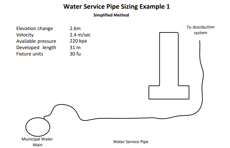
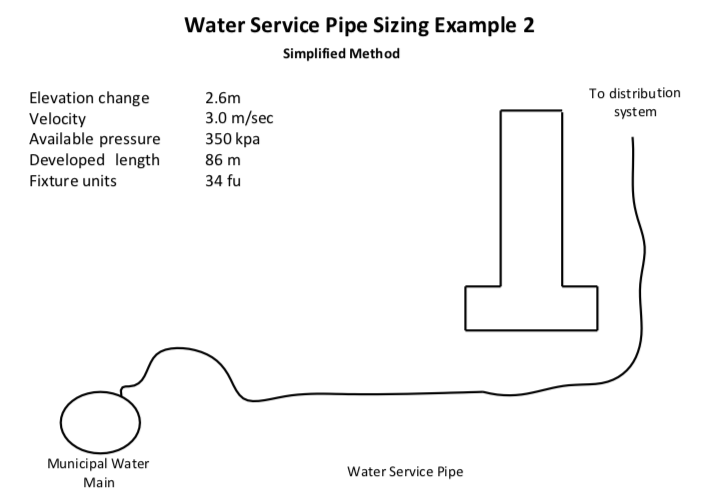
With example #1 complete note the changes in elevation, velocity and other details written below in example #2. Once finished sizing the water service pipe share the answers with your instructor to confirm the correct answer was achieved.
Sizing Water Pipe in a Small Commercial Building
A.2.6.3.1. (2)
The method for sizing water pipe in larger installations is based on the National Plumbing Code of Canada. This sizing method is adequate for sizing the water piping for buildings that require a 2 1/2” size or smaller.
Now please refer to the National Plumbing Code of Canada for the following exercise.
The water pipe sizing method presented here for larger installations uses five tables: Table 2.6.3.2.A., Table 2.6.3.2.B., Table 2.6.3.2.C. and Table 2.6.3.2.D. and Appendix Table A-2.6.3.1.(2)A.
Table 2.6.3.2.A.
Fu load for fixtures, private and public – use Total column only
Table 2.6.3.2.B.
Fu load for multiple Urinals with flush valves
1 FV urinal = 20 FU
3 FV urinals = 45 FU
Table 2.6.3.2.C.
Fu load for multiple WC with flushvalves
1 FV WC = 40 FU
3 FV WC = 90 FU
Table 2.6.3.2.D.
• Fixtures not listed on Table Table 2.6.3.2.A.
Table A-2.6.3.1.(2)A.
This table is actually three tables for water supply pressures in three different pressure ranges:
- 200 to 310 kPa
- 311 to 413 kPa
- Over 413 kPa
There are four steps used in sizing a water system as outlined in section A-2.6.3.1. (2). For the purpose this course we are only concerned with steps 1 and 2
- Determine which pressure range and developed length from Table A-2.6.3.1. (2)A.
- Size the Water Service Pipe
- Size the Hot Water Piping
- Size the Cold Water Piping
Small Commercial Building
Prior to starting the sizing project, please read article A-2.6.3.1.(2). Potable Water Systems and note that there are basically five conditions that need to be established to be able to size a project with this method:
Determine the Pressure Range for Table A-2.6.3.1.(2)
- Developed Length
- Main to meter location – sizing water service pipe
- Meter to most distant outlet – sizing distribution system
- Minimum Static Pressure
- Minimum static pressure at the property line
- Fluctuations – Minimum static pressure
- Pressure Losses
- Meters, PRV’s and Backflow devices
- Elevations
- Service – property line to meter location
- Distribution – meter location to highest outlet
- FU
- Use Total FU Column – private or public
- Flow Velocities
- Maximum – manufacture’s recommendations
Sizing the Water Service Pipe
- Total FU of all outlets
- Minimum static pressure at the property line
- Minus elevation difference between property line and meter location
- Select pressure range Table A.2.6.3.1.(2)A.
- Developed length
- Property line to the meter location
- Find the developed length column and the Total FU and follow the row back to the left to the first column (water service pipe).
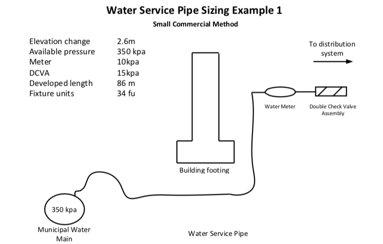
For the example above please note there is a elevation change between the Municipal water main and the water meter so that pressure loss is required to be subtracted from the total given below as the available pressure in the Municipal water main.
Once the pressure, elevation and other losses of pressure are calculated you should have 324kpa with a developed length of 86 meters and 34 fixture units.
Select the appropriate table from the three tables in the code book in the notes section towards the back of your code book. With a pressure of 324 kps you will use the table Pressure Range 311-413
Look across the top of the table to developed length of 86 you will jump up to 91 meters and scroll down to 34 fixture units you will have to go up to 39.
Notice the light grey color that the square is shaded with, this signifies a flow velocity of 2.4 m/sec.
Once this step is complete you can look over to the left to the water service pipe column and find a size of 1 ½”.
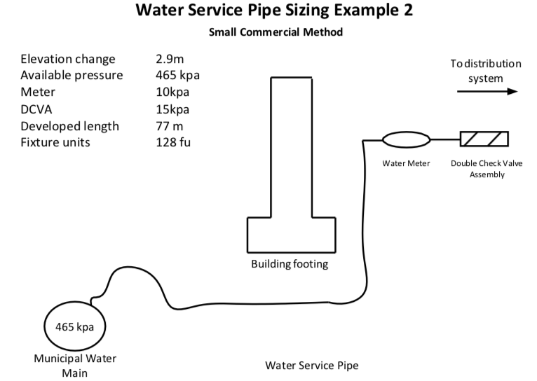
Take a few minutes to research the water service pipe for example #2 using the same steps used for #1.
WATER PIPE TESTING
Potable water testing is covered in the National Plumbing Code at 2.3.7.1., 2.3.7.2. and 2.3.7.3.
An air test is carried out by blanking off all open ends and applying pressure into the system as required by 2.3.7.
The entire system may be tested at once or by sections depending on the size of the system. One problem that may arise is that small leaks are difficult to detect. An approved leak detector (soap and water) may need to be applied to each joint until the leak/s are found.
Sometimes nitrogen is used for small systems or quick tests.
Water may also be used to test the system however temperature and the possibility of water damage must be considered. As stated in the code potable water must be used.
-
-
- Pex piping may lose pressure through the pipe walls when testing with air. A slight air loss is normal when testing Pex.
- Ambient temperature will cause the pressure inside the pipe to increase or decrease.
- Copper pipe will not leak air, but ambient temperatures will affect the pressure.
-