
10.2 Adjustment and Maintenance
Adjusting the length of the flush
Adjustment screw (Located on opposite side of handle).
When the regulating screw (needle control valve) on the top opposite the handle is screwed down, the size of the bypass opening is reduced, it now takes longer for the upper chamber to fill with water which in turn causes a longer flush.
When the regulating screw (needle control valve) on the top opposite the handle is screwed upwards, the size of the bypass opening is enlarged, it now takes less time for the upper chamber to fill with water which in turn causes a shorter flush.
Note
- The length of the flush on a flushometer with the center screw is shortened if the adjustment screw is turned down.
- The length of the flush on a flushometer with the screw opposite the handle is longer when the adjustment screw is turned down.
The length of the flush depends on how fast the upper chamber fills with water.
Shorter or longer flush
Turn regulating screw LEFT to shorten flush and RIGHT to lengthen. When turned too far RIGHT, the valve will flush continuously.
Stop Continuous Flushing
Make sure regulating screw is not turned too far to the RIGHT (see above). If flush is still continuous, remove Regulating Screw, clean the by-pass slot and replace it in the valve. Adjust slowly for proper flush.
Sudden Closing Off
When a valve will only flush while the handle is depressed, the Diaphragm is worn and requires replacing.
Excessive Noise
To reduce noise, partially close stop.
Shortage of Water
Fully open stop. Check pipeline for size or obstruction. Check water pressure. A Flushometer requires a 1″ water supply and batteries (Groups) of valves require larger diameter pipe. Where a battery of toilets are installed several may be required to flush at one time, therefore, it is important to check the pipe line size. The usual reason for a slow lazy flush is shortage of water caused by a corroded or undersize water piping.
Prevent Water Hammer
A water hammer arrester should be installed at the end of a battery of flushometers and at the back of on individual installation. This assures smoother operation of the valves and a longer life for parts.
Replace cap and diaphragm correctly.
When the Flushometer has been token apart and reassembled and does not operate, check to make sure that Cap has been put on the body properly. The indicating arrow labeled “handle” on top of the cap should point to the handle of the valve.
Slight Water Leak
Examine the seating surface of the Diaphragm Seat for embedded sediment. Examine the seating surface of Relief Valve and Disc for wear. It may be necessary to replace one or all of these parts.
Leak at Handle
When the handle is depressed for a flush and there is a leak between the handle and the bonnet, replace the “0” ring in the handle assembly.
Adjusting the Length of the Flush
When the Regulating Screw (needle bypass valve) on top of the flushometer is screwed down, the diaphragm is prevented from lifting up which reduces the volume of water that escapes out of the upper chamber. The water enters the upper chamber through the bypass orifice which fills the upper chamber. The faster the upper chamber fills the shorter the flush.
Backflow Preventers
Vacuum breakers or backflow preventers should be installed on flush valves serving water closets to prevent cross-connection in case of a pressure drop in the supply line.
The vacuum breaker provides positive protection against pollution of the pure water supply by preventing back syphonage from the fixture through a flush valve. Back syphonage is a process whereby water standing in a fixture and possibly contaminated, may be drawn back into the supply lines by suction resulting from partial vacuum or backflow in the supply pipes. This suction may be caused by a water-main being damaged or water system being shut off and drained.
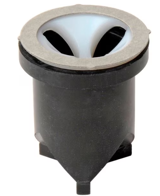
- The vacuum breaker is made from natural rubber and is installed inside the chrome outlet pipe.
- The flushometer valve is flushed, the opening in the vacuum breaker allows the water to flow to the fixture. At the same time, the vacuum breaker seals off the air vents in the outlet pipe.
- If a vacuum occurs in the supply line, the vacuum breaker collapses and allows air to enter through the air vents in the outlet pipe. The cross bar at the top of the vacuum breaker prevents the vacuum breaker from being drawn into the valve.
Image Credit
- Zoro. (n.d.). Flushometer Vacuum Breaker Repair Kit, V-551-A. https://www.zoro.com/sloan-regal-flushometer-vacuum-breaker-repair-kit-v-551-a-3323192/i/G708663078/