
5.4 Frequency Response and Noise
Like compliance and distortion, two other practical limits on amplifier performance are its frequency response and output noise. First, let’s discuss frequency response.
Although we describe an amplifier as having a specific gain or amplification factor, this is true only for a certain range of frequencies. All amplifiers are limited in terms of the range of frequencies over which they can operate. If we examine an amplifier’s performance at extreme frequencies, the gain may be much less than the nominal value. In fact, if we go far enough, the gain may even be fractional, meaning that the “amplifier” is actually reducing the signal level.
The region where the nominal gain is accurate is referred to as the mid-band. This range is defined by one or two corner or break frequencies. The lower limit is referred to as f1 while the upper limit is referred to as f2 . At these frequencies, the output level has dropped to half the power exhibited by a mid-band frequency of the same input level. A gain versus frequency response plot that encapsulates this concept is shown in Figure 5.4.1.
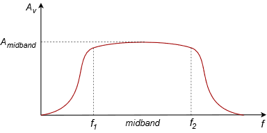
In this representative plot it is apparent that only input signals whose frequencies lay between f1 and f2 will receive full amplification. As the input frequency moves to either side of the middle band, the gain begins to drop off. The drop-off increases as the signal frequency moves farther and farther away. Eventually the gain will fall to practically zero and virtually no trace of the input signal will appear at the output.
Precise values of the corner frequencies will depend on the application. For example, a high fidelity audio amplifier will most likely have an f1 below 20 Hz and an f2 above 20 kHz21 while an amplifier used for telephone systems might range from 300 Hz to 4 kHz22. In contrast, a radio frequency amplifier may be operating at frequencies orders of magnitude higher than these.
Without exception, all amplifiers have an upper limit frequency, f2 , but not all of them have a lower frequency limit, f1 . Amplifiers without a lower limit can amplify signals with frequencies all the way down to DC. They are referred to as direct coupled or DC amplifiers. The lower frequency limit is usually caused by in-line coupling capacitors, and in some cases, transformers. Among other uses, these components are added to purposely block DC. There are good reasons to do this, as we shall see in upcoming work, however, it is possible to design amplifiers without them. The resulting amplifier will then have no limit on how low of a frequency it can amplify.
The upper limit frequency is another story. While components are often added to tailor the upper frequency response of an amplifier, even if no tailoring was desired the amplifier would still have an upper limit frequency. This would be due to small and unavoidable capacitances and inductances that exist in the circuit, for example stray wiring capacitance. Ultimately, the corresponding reactances will cause a signal level reduction that worsens as frequency increases. As you might guess, these reactances also cause varying phase shifts between the input signal and the output signal.
Amplifier performance is also limited by its internal noise. Noise is an undesired signal that appears at the output of an amplifier. Unlike distortion, noise is usually not correlated with the input signal level. Generally, noise is broad-band, meaning that it contains a very wide range of frequencies. As such, it does not have a discernible pitch. Examples in nature include the sound of leaves rustling in the wind or the sound of a waterfall. Noise is best thought of as a truly random signal. As such, it cannot be accurately predicted and therefore there is no easy way to remove it once it has been added to a desired signal. There are many potential sources of noise in an amplifier. They range from process issues in semiconductors to thermal effects in resistive elements. In general, noise gets worse as temperature, resistance and frequency range increase. Noise is unavoidable in absolute terms but ultimately what we care about is whether or not it is low enough for a given application. In other words, is the noise level significantly lower than the signal level, to the point where it is no longer a problem? This is quantified by simply creating a ratio between the nominal output signal level and the output noise level. This ratio is given the very creative name signal-to-noise ratio, or S/N for short. All other factors being equal, the higher the S/N, the better.
References
120 Hz – 20 kHz is the range of frequencies heard by a typical healthy young human.
2Decidedly not hi-fi, but do we really need high fidelity to call-in a take-out order?
