5.5 Miller’s Theorem
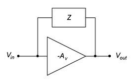
Some inverting voltage amplifier designs employ an impedance bridged between the input and output, as shown in Figure 5.5.1.

There are different reasons for doing this, a prime example involving shaping the frequency response of the amplifier. To simplify the analysis of such a configuration, we may employ Miller’s Theorem, named after American engineer John Milton Miller.
The goal here is to determine equivalent impedances that lie in parallel with the input and output of the amplifier. These equivalents simply become part of the input and output networks around the amplifier.
First, let’s consider the equivalent impedance at the input, Zin−miller . By definition, this is the impedance in parallel with the input of the amplifier that would draw the same amount of current as the original bridging Miller impedance. The current through the Miller impedance is simply the the voltage across it divided by the Miller impedance, Z . The voltage across it is the difference between the input and output voltages.
![]()
![]()
![]()
Dividing this current into the input voltage yields the equivalent impedance.
![]()
A similar derivation yields the output equivalent.
![]()
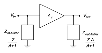
The Miller equivalent circuit for a general impedance Z is shown in Figure 5.5.2.

The general rule to remember is that the Miller equivalent presents equivalent impedances that are less than the original bridging impedance. In the case of the input section, the reduction effect is very large at higher gains.
Two typical cases for the impedance Z are a resistance, R, and a capacitance, C. For a pure resistance, we can perform a direct substitution for Z . The original and Miller equivalents are shown in Figure 5.5.3

For a capacitor, the situation is similar, however, we will substitute Xc for Z and recall that C = 1/(2πf Xc).

Note that for the capacitor, there is a multiplicative effect. That is, the effect of the original bridging capacitor on a high gain amplifier is equivalent to a much larger input shunt capacitor..

