
1.7 Exercises
Assume diodes are silicon unless stated otherwise
Analysis Problems
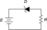
- For the circuit of Figure 1.7.1 determine the circulating current if the supply is 6 volts and the resistor is 10 kΩ.
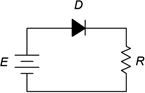
- Repeat Problem 1 if the diode is inserted in the opposite orientation.
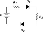
- Given the circuit of Figure 1.7.2, determine the voltage drops across the resistors. The source is 12 volts, R1 = 4.7 k and R2 = 3.3 k.
- In Figure 1.7.3 determine the voltage drops across the resistors.
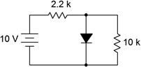
Figure 1.7.3
- Determine the LED current in Figure 1.7.4. Assume the LED barrier is 2.1 volts, the source is 5 volts and the resistor is 330 Ω.
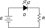
- Repeat Problem 5 if the LED is inserted in reverse orientation.
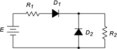
- Determine the resistor currents in Figure 1.7.5. The source is 15 volts, R1 = 8.2 k and R2 = 3.9 k.
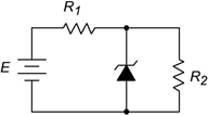
- For the circuit of Figure 1.7.6, determine the resistor voltage. The source is 9 volts, the Zener potential is 5.1 volts and the resistor is 1 k.

- For the circuit of Figure 1.7.7, determine the resistor voltage. The source is 8 volts, the Zener potential is 3.3 volts and the resistor is 10 k.
- Determine the voltage across R2 in Figure 1.7.8 if the source is 9 volts, the Zener is 6.8 volts, R1 = 5.1 k and R2 = 33 k.
Challenge Problems
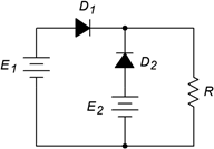
- Determine the resistor voltage in Figure 1.7.9 if E1 = 5 volts, E2 = 9 volts and R= 1 k.

- Determine the voltage across R2 in Figure 1.7.8 if the source is 9 volts, the Zener is 5.6 volts, R1 = 5.1 k and R2 = 3.9 k.
Design Problems
- Determine a value for R in Figure 1.7.1 to set the current to 10 mA if the source is 5 volts.
- Determine a value for R in Figure 1.7.4 that will set the LED current to approximately 20 mA if the source is 9 volts and the LED is a standard red type. Use a standard resistor value.
Computer Simulation Problems
- Simulate Problem 9.
- Simulate the circuit designed in Problem 14 for verification.
