3.9 Exercises
Assume diodes are silicon unless stated otherwise
Analysis Problems
- Determine β if α = 0.99
- Determine α if β = 200
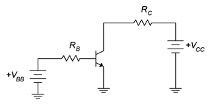
- Determine the currents for the circuit of Figure 3.9.1 if VBB = 5 V, VCC = 20 V,
RB = 200 kΩ, RC = 2 kΩ, β = 100. - Determine the transistor voltages for the circuit of Figure 3.9.1 if VBB = 5 V, VCC = 20 V,
RB = 200 kΩ, RC = 2 kΩ, β = 200.
Figure 3.9.1 - Determine the LED current in the circuit of Figure 3.9.2 if Vlogic = 5 V, VCC = 5 V,
VLED = 2.1 V, RB = 3.6 kΩ, RC = 270 Ω, β = 100. - Determine the LED current in the circuit of Figure 3.9.2 if Vlogic = 0 V, VCC = 5 V,
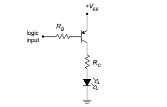
VLED = 2.1 V, RB = 3.6 kΩ, RC = 270 Ω, β = 100. - Determine the LED current in the circuit of Figure 3.9.3 if Vlogic = 5 V, VEE = 5 V,
VLED = 2.2 V, RB = 2.7 kΩ, RC = 220 Ω, β = 100.
Figure 3.9.3 - Determine the LED current in the circuit of Figure 3.9.3 if Vlogic = 0 V, VEE = 5 V,
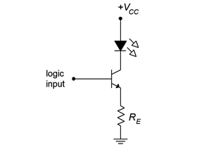
VLED = 2.2 V, RB = 2.7 kΩ, RC = 220 Ω, β = 100. - Determine the LED current in the circuit of Figure 3.9.4 if Vlogic = 3.6 V, VCC = 10 V,
VLED = 2.3 V, RE = 270 Ω, β = 200.
Figure 3.9.4 - Determine the LED current in the circuit of Figure 3.9.4. Vlogic = 0 V, VCC = 10 V,
VLED = 2.3 V, RE = 270 Ω, β = 200. - Using the 2N3904 data sheet, determine VCE(sat) if IC = 30 mA and IB = 1mA.
- Using the 2N3904 data sheet, determine the percent change in β if IC = 10 mA and the temperature rises from 25°C to 125°C.
- Using the 2N3904 data sheet, determine the percent change in β if IC = 40 mA and the temperature drops from 25°C to −55°C.
Design Problems
- Using Figure 3.9.1, determine a value for RB to set IC to 5 mA if VBB = 5 V, VCC = 25 V,
RC = 2 kΩ, β = 100. - Using Figure 3.9.1, determine a value for RC to set VCE to 6 V if VBB = 10 V, VCC = 25 V,
RB = 330 kΩ, β = 200. - For the circuit of Figure 3.9.2, determine a value for RC to set the LED current to 15 mA. Vlogic = 5 V, VCC =5 V, VLED = 1.6 V, RB = 3.3 kΩ.
- For the circuit of Figure 3.9.3, determine a value for RC to set the LED current to 20 mA. Vlogic = 0 V, VEE = 5 V, VLED = 2.0 V, RB = 2.7 kΩ.
- For the circuit of Figure 3.9.4, determine a value for RE to set the LED current to 25 mA. Vlogic = 5 V, VCC = 9 V, VLED = 2.8V.
Challenge Problems
- Determine the maximum and minimum values for IC in the circuit of Figure 3.9.1 if all resistors have a 10% tolerance and β = ranges from 100 to 200.
VBB =5 V, VCC = 20 V, RB = 200 kΩ, RC = 2 kΩ. - Derive and draw a PNP non-saturating LED driver circuit.
Computer Simulation Problems
- Simulate the circuit of Problem 3.
- Simulate the circuit of Problem 5.
- Simulate the circuit of Problem 7.
- Verify the design of Problem 14 using a simulator.

