
3 Diode Curves
Learning Objective
Theory Overview
The basic diode is an asymmetric non-linear device. That is, its current-voltage characteristic is not a straight line and it is sensitive to the polarity of an applied voltage or current. When placed in forward bias (i.e. positive polarity from anode to cathode), the diode will behave much like a shorted switch and allow current flow. When reversed biased the diode will behave much like an open switch, allowing little current flow. Unlike a switch, a silicon diode will exhibit an approximate 0.7 volt drop when forward biased. The precise voltage value will depend on the semiconductor material used. This volt drop is sometimes referred to as the knee voltage as the resulting I-V curve looks something like a bent knee.
The effective instantaneous resistance of the diode above the turn-on threshold is very small, perhaps a few ohms or less, and is often ignored. Analysis of diode circuits typically proceeds by determining if the diode is forward or reversed biased, substituting the appropriate approximation for the device, and then solving for desired circuit parameters using typical analysis techniques. For example, when forward biased, a silicon diode can be thought of as a fixed 0.7 volt drop, and then KVL and KCL can be applied as needed. The polarity of the device is typically denoted by a band placed closest to the cathode.
Equipment
| (1) Adjustable DC power supply | model: | srn: |
| (1) DMM | model: | srn: |
| (2) Signal diodes (1N4148, 1N914) | ||
| (1) 1 k Ω resistor ¼ watt | actual: | |
| (1) 10 k Ω resistor ¼ watt | actual: | |
| (1) 4.7 k Ω resistor ¼ watt | actual: | |
Link
Schematics
Procedure
Forward Curve
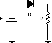
- Consider the circuit of Figure 1 using R = 1 kΩ. For any positive value of E, the diode should be forward biased. Once E exceeds the knee voltage, all of E (minus approximately 0.7 volts) drops across R. Thus, as E increases, so does the diode current.
- Build the circuit of Figure 1 using R = 1 kΩ. Set E to 0 volts and measure both the diode’s voltage and current and record the results in Table 1. Remember, voltage is measured across a device (parallel) while current is measured through it (series). Repeat this process for the remaining source voltages listed.
- From the data collected in Table 1, plot the current versus voltage characteristic of the forward biased diode. Make sure VD is the horizontal axis with ID on the vertical.
Reverse Curve
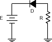
- Consider the circuit of Figure 2 using R = 1 kΩ. For any positive value of E, the diode should be reversed biased. In this case, the diode should always behave like an open switch and thus no current should flow. If no current flows, the voltage across R should be zero, and thus the diode voltage should be equal to the applied source voltage. Note that the diode’s voltage polarity is negative with respect to that of Figure 1.
- Build the circuit of Figure 2 using R = 1 kΩ. Set E to 0 volts and measure both the diode’s voltage and current and record the results in Table 2. Repeat this process for the remaining source voltages listed.
- From the data collected in Table 2, plot the current versus voltage characteristic of the reverse biased diode. Make sure VD is the horizontal axis with ID on the vertical.
Practical Analysis
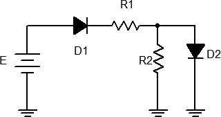
- Consider the circuit of Figure 3 using E = 12 volts, R1 = 10 kΩ and R2 = 4.7 kΩ. Analyze the circuit using the ideal 0.7 volt forward drop approximation and determine the voltages across the two resistors. Record the results in the first two columns of the first row (Variation 1) of Table 3.
- Build the circuit of Figure 3 using E = 12 volts, R1 = 10 kΩ and R2 = 4.7 kΩ. Measure the voltages across the two resistors. Record the results in columns three and four of the first row (Variation 1) of Table 3. Also compute and record the percent deviations in columns four and five.
- Reverse the direction of D1 and repeat steps 7 and 8 as Variation 2 in Table 3.
- Return D1 to the original orientation and reverse the direction of D2. Repeat steps 7 and 8 as Variation 3 in Table 3.
- Reverse the direction of both D1 and D2, and repeat steps 7 and 8 as Variation 4 in Table 3.
Computer Simulation
- Repeat steps 7 through 11 using a simulator, recording the results in Table 4.
Data Tables
| E (volts) | VD | ID |
|---|---|---|
| 0 | 0 | |
| 0.5 | ||
| 1 | ||
| 2 | ||
| 4 | ||
| 6 | ||
| 8 | ||
| 10 |
| E (volts) | VD | ID |
|---|---|---|
| 0 | ||
| 1 | ||
| 2 | ||
| 5 | ||
| 10 | ||
| 15 |
| Variation | VR1 Theory | VR2 Theory | VR1 Exp | VR2 Exp | % Dev VR1 | % Dev VR2 |
|---|---|---|---|---|---|---|
| 1 | ||||||
| 2 | ||||||
| 3 | ||||||
| 4 |
| Variation | VR1 Sim | VR2 Sim |
|---|---|---|
| 1 | ||
| 2 | ||
| 3 | ||
| 4 |
Questions
- Is 0.7 volts a reasonable approximation for a forward bias potential? Is an open circuit a reasonable approximation for a reverse biased diode? Support your arguments with experimental data.
- The “average” resistance of a forward biased diode can be computed by simply dividing the diode’s voltage by its current. Using Table 1, determine the smallest average diode resistance (show work).
- The instantaneous resistance (also known as AC resistance) of a diode may be approximated by taking the differences between adjacent current-voltage readings. That is, rdiode = ΔVdiode/ΔIdiode. What are the smallest and largest resistances using Table 1 (show work)? Based on this, what would a plot of instantaneous diode resistance versus diode current look like?
- If the circuit of Figure 3 had been constructed with LEDs in place of switching diodes, would there be any changes to the values measured in Table 3? Why/why not?
