
10 Full-wave Bridge Rectifier
Learning Objective
The objective of this exercise is to investigate the operation of a full-wave bridge rectifier as part of an AC to DC power supply. Also included are the effects of loading and filter capacitance.
Theory Overview
The full-wave bridge, like the half-wave rectifier, is used to turn an AC signal into pulsating DC. The full- wave bridge requires four diodes instead of one but has the advantage of utilizing the opposite polarity of the signal, effectively flipping its polarity rather than simply “throwing it away” like the half-wave circuit. This increases the energy available to the load and lessens the burden on filtering capacitors as the resulting gap between pulses is much smaller.
Equipment
| (1) Dual channel oscilloscope | model: | srn: |
| (1) DMM | model: | srn: |
| (4) Rectifying diodes (1N4002 series) | ||
| (1) 12.6 volt 1 amp center tapped transformer | ||
| (1) 1 k Ω resistor ¼ watt | actual: | |
| (1) 20 Ω resistor 20 watt | actual: | |
| (1) 1000 µF capacitor 25 volt | actual: | |
Link
Download the datasheet:
Schematic
Procedure
Basic Operation
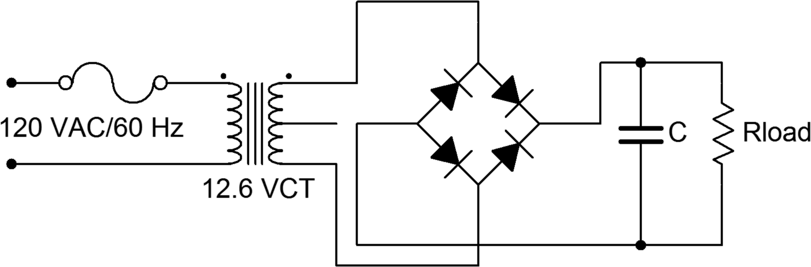
- First, note that the circuit of Figure 1 is being powered directly from the AC line. Treat it with appropriate caution. It is worth repeating that any circuit should be de-energized when making any changes to it.
- Consider the circuit of Figure 1 without the capacitor connected. For a positive polarity of secondary voltage, the upper right and lower left diodes will be forward biased and allow current to flow through the load from top to bottom. The other two diodes will be reverse biased. For a negative secondary polarity the opposite occurs. That is, the upper left and lower right pair will be forward biased while the other two are reverse biased. This arrangement will also cause load current to flow through the load from top to bottom, thus effectively flipping the negative polarity portion of the wave.
- Build the circuit of Figure 1 with Rload = 1 kΩ and C disconnected (open). This represents a very lightly loaded case. Under light loads, the output of the secondary will often be a little higher than the rated potential. Set the oscilloscope input to DC coupled. Measure and record the voltage across the secondary and then across the load. Do not use two probes to do this simultaneously as these two measurements do not share a common ground. Doing so will short out a portion of the circuit. Record the results in Table 1 and capture an image of the load voltage display.
- Measure the load voltage with a DMM set to DC volts. Record this value in Table 1.
- Replace the load with the 20 Ω resistor to simulate greater loading. Repeat steps 3 and 4.
- Return the load resistor to the original 1 kΩ value and insert the 1000 µF capacitor. Measure the load voltage with both the oscilloscope and DMM, recording the values in Table 2. Be sure to capture an image of the scope display.
- Replace the load with the 20 Ω resistor to simulate greater loading. Measure the load voltage with both the oscilloscope and DMM, recording the values in Table 2. Once again, be sure to capture an image of the scope display.
Computer Simulation
- Simulate the circuit of Figure 1 using Transient Analysis. Use three variations, comparing the plotted waveforms to those measured in the laboratory: C = open with Rload = 20 Ω, C = 1000 μF with Rload = 1 kΩ, and C = 1000 μF with Rload = 20 Ω.
Data Tables
| Load | Vsecondary scope | Vload scope | Vload DMM |
|---|---|---|---|
| 1 kΩ | |||
| 20 Ω |
| Load | Vload scope | Vload DMM |
|---|---|---|
| 1 kΩ | ||
| 20 Ω |
Questions
- What is the effect on the load voltage as the loading increases (i.e., as Rload decreases)?
- What is the effect of adding the capacitor across the load?
- How do the load voltages as measured by the DMM compare to those measured with the oscilloscope? Is there a pattern between the pairs of measurements?
- How would the load voltages change if the diode bridge is connected between one end of the secondary and the center tap instead of across the entire secondary?
