
9 The Transformer
Learning Objective
Theory Overview
A power transformer is used to change an AC voltage from one amplitude to another, ideally without power loss. This is accomplished through a magnetic circuit consisting of a metallic core wrapped with primary and secondary windings of wire. The ratio of the number of primary windings to secondary windings is called the turns ratio. The voltage at the secondary can be increased or decreased depending on this ratio. In the ideal case, or lossless transformer, the product of secondary voltage and current will equal the product of primary voltage and current. That is, the ideal transformer does not dissipate power itself, but rather transforms power from one scenario to another. Real transformers dissipate some power because the copper wires have finite resistance and the magnetic coupling is not 100% efficient. The lost energy is often found in the form of heat. Another important characteristic of the transformer is that it creates electrical isolation between the primary and secondary. In other words, the circuit common points do not have to be the same potential or tied together between the primary and secondary sides.
Typically, power transformers are rated for a given input voltage and frequency (120 VAC/60 Hz in North America) which yields a specified secondary voltage under load. If the load current is minimal, the secondary voltage tends to increase beyond the rated value. This is due to the resistance of the windings and can be reduced by using a larger gauge although this results in a larger transformer. Also, it is common for secondaries to be split or to have a center tap. A center tap allows the secondary to be treated as two symmetrical halves. This is useful for circuit rectification circuits. Finally, dots drawn on the transformer’s schematic symbol and connections indicate like instantaneous polarity on the primary and secondary. That is, when the primary voltage is positive at its dot, the secondary voltage will also be positive at its dot.
Equipment
| (1) Dual channel oscilloscope | model: | srn: |
| (1) Function generator | model: | srn: |
| (1) DMM | model: | srn: |
| (1) 12.6 volt, 1A center tapped transformer | ||
| (1) 10 Ω resistor ¼ watt | actual: | |
| (1) 22 Ω resistor ¼ watt | actual: | |
| (1) 20 Ω resistor 20 watt | actual: | |
Link
Download the datasheet:
- 1N4148/1N914 Datasheet
Schematics
Procedure
Low Voltage
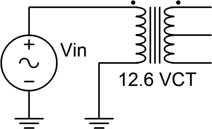
- Consider the circuit of Figure 1. With a 12.6 volt secondary rating and a 120 volt primary rating, the turns ratio is approximately 10:1. In other words, for any reasonable input signal at the primary, the output at the secondary is expected to be one tenth the voltage and ten times the current.
- Connect the primary side of the transformer to the function generator as shown in Figure 1. Set the generator to a 10 volt peak sine at 60 Hz. Place the oscilloscope probe grounds at the bottom of the secondary. Connect probe tip one to the top of the secondary and probe tip two to the center tap. Record the peak amplitudes in Table 1 and capture an image of the scope display. Compute and record the primary/secondary voltage ratio as well (for the full secondary).
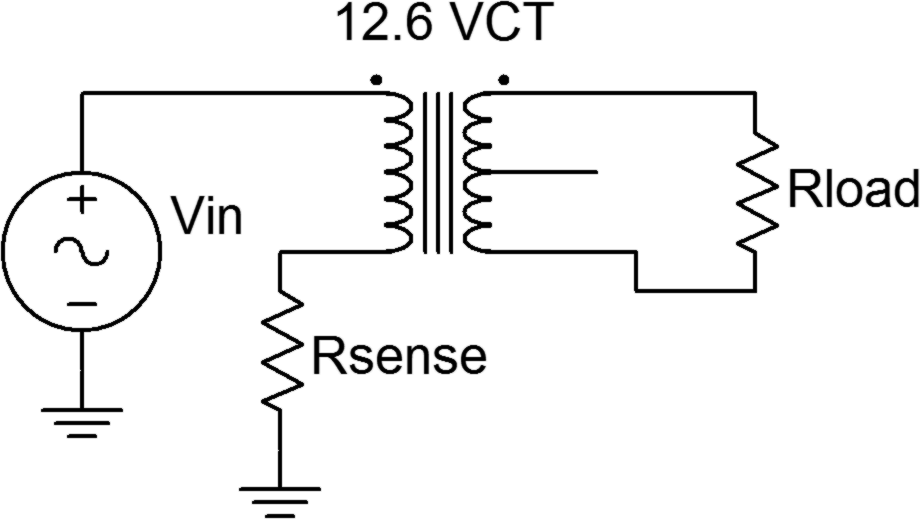
- Build the circuit of Figure 2 using Rsense = 22 Ω, Rload = 10 Ω and Vin = 5 volt peak sine at 60 Hz. Place one scope probe across the load and the other across Rsense. Record the peak amplitudes in Table 2 and capture an image of the scope display.
- Using the voltage measured across the sense resistor, determine the primary side current. Using Ohm’s law and the measured load voltage, determine the load (i.e., secondary) current. Based on these, compute the primary/secondary current ratio. Record these values in Table 2.
Line Voltage
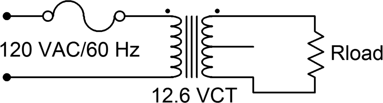
- This section uses the 120 VAC line. Treat it with the caution it deserves. Connect the circuit of Figure 3 leaving Rload unconnected. Measure the secondary voltage with the DMM (AC Volts). Record the value in Table 3 under “Unloaded”.
- Add the load resistor, 20 Ω, and measure the load voltage with the DMM. Record the value in Table 3 under “Loaded”. Determine the percent change between the loaded and unloaded voltages. Also, measure the load voltage using the oscilloscope and capture an image of the display.
Data Tables
| Full Secondary Voltage | |
| Center Tap Voltage | |
| Pri/Sec Voltage Ratio |
| Primary Sense Voltage | |
| Primary Current | |
| Secondary Voltage | |
| Secondary Current | |
| Pri/Sec Current Ratio |
| Vload Unloaded | |
| Vload Loaded | |
| Percent Change |
Questions
- Examining the results of the circuit in Figure 1, does the specified turns ratio match that which is found experimentally? Why/why not?
- What is the effect of loading on a transformer’s secondary voltage?
- Does the primary/secondary voltage ratio complement the primary/secondary current ratio? What does this say about the power dissipation of the transformer?
- Are there appreciable variations between using the transformer at high input voltages versus low input voltages?
