
4 Light Emitting Diodes
Learning Objective
Theory Overview
The LED is similar to the ordinary signal or rectifying diode in that it is polarity sensitive. In reverse bias the device behaves as an open and prevents current flow. In forward bias, the device allows current flow once its forward barrier potential is reached. This potential is significantly higher than that of ordinary diodes and depends on the material used, and hence, the color that is displayed. Generally, luminous intensity is a function of the forward current. That is, the greater the current, the brighter the output. In operation, a series limiting resistor or other control device must be used to limit the forward current and prevent damage that could occur to the LED from excessive current. Different technologies are used in the design and production of LEDs and there are many variations including full spectrum (white) and high brightness versions. The cathode of an LED is typically denoted by a flat spot on the plastic casing and/or by the shorter of the two leads.
Equipment
| (1) Adjustable DC power supply | model: | srn: |
| (1) DMM | model: | srn: |
| (1) Each of standard LEDs of various colors (red, blue, green, yellow) | ||
| (1) High brightness white LED | ||
| (1) 1 k Ω resistor ¼ watt | actual: | |
Links
Download the datasheets listed below:
Schematics
Procedure
Forward Curve
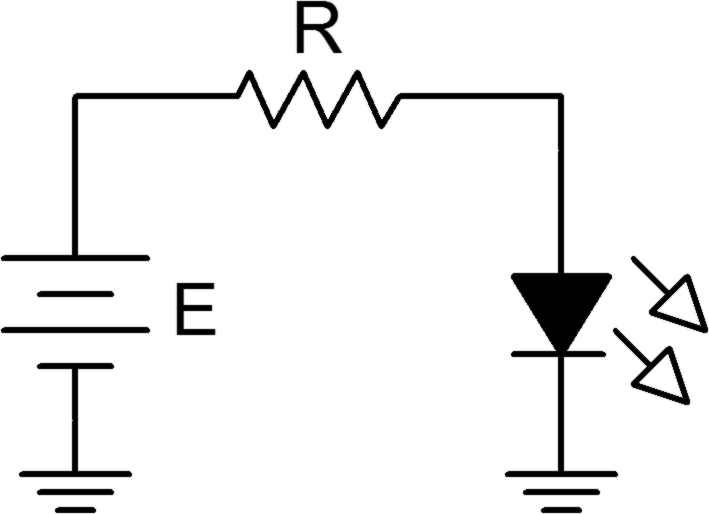
- Consider the circuit of Figure 1 using R = 1 kΩ. For any positive value of E, the diode should be forward biased. Once E exceeds the knee voltage, the difference between the source and the knee drops across R. Thus, as E increases, so does the LED current and hence its brightness.
- Build the circuit of Figure 1 using R = 1 kΩ and the red LED. Set E to 0 volts and measure both the LED voltage and current and record the results in Table 1. Note the relative brightness level. Repeat this process for the remaining source voltages listed.
- From the data collected in Table 1, plot the current versus voltage characteristic of the forward biased LED. Make sure VD is the horizontal axis with ID on the vertical.
- Repeat steps 2 and 3 for the blue LED using Table 2.
- If other colors are available repeat steps 2 and 3 for them using Table 3 (create other tables as needed).
High Brightness
- Replace the LED of Figure 1 with the high brightness white LED. Set the supply to 12 volts. Record the LED voltage, current and brightness in Table 4.
Reverse Curve
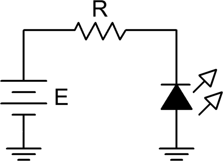
- Consider the circuit of Figure 2 using R = 1 kΩ. For any positive value of E, the LED should be reversed biased. In this case, the LED should always be open causing no current to flow. If no current flows, the LED produces no light. Also, the voltage across R should be zero, and thus the LED voltage should be equal to the applied source voltage. Note that the LED voltage polarity is negative with respect to that of Figure 1.
- Build the circuit of Figure 2 using R = 1 kΩ using the red LED. Set E to 0 volts and measure both the LED voltage and current and record the results in Table 5. Repeat this process for the remaining source voltages listed.
- From the data collected in Table 5, plot the current versus voltage characteristic of the reverse biased diode. Make sure VD is the horizontal axis with ID on the vertical.
Data Tables
| E (volts) | VD | ID | Brightness |
|---|---|---|---|
| 0 | |||
| 1 | |||
| 2 | |||
| 3 | |||
| 4 | |||
| 6 | |||
| 12 |
| E (volts) | VD | ID | Brightness |
|---|---|---|---|
| 0 | |||
| 1 | |||
| 2 | |||
| 3 | |||
| 4 | |||
| 6 | |||
| 12 |
| E (volts) | VD | ID | Brightness |
|---|---|---|---|
| 0 | |||
| 1 | |||
| 2 | |||
| 3 | |||
| 4 | |||
| 6 | |||
| 12 |
| E (volts) | VD | ID | Brightness |
|---|---|---|---|
| 12 |
| E (volts) | VD | ID |
|---|---|---|
| 0 | ||
| 1 | ||
| 3 | ||
| 8 |
Questions
- Is the forward knee voltage of an LED comparable to that of ordinary switching and rectifying diodes?
- Are the knee voltages of LEDs consistent across colors?
- Compare the reverse characteristics of LEDs and switching diodes.
- What can be said regarding LED brightness and current?
