
5 Photodiodes
Learning Objective
Theory Overview
The photodiode is, in essence, the reverse of the LED. In fact, depending on their design, LEDs can be used as a type of photodiode. Photodiodes are responsive to light in one of two ways. The first method is the photovoltaic mode. In this mode, a voltage appears across the PN junction that is proportional to the amount of light striking it. It can be thought of as a small voltage source or battery. The second mode is photoconductive. In this mode, the photodiode is reverse biased by an external DC supply. The amount of current flowing through the diode will be proportional to the amount of light striking the junction.
Typically, this current will pass through a series resistor to create a voltage or it can be sent into a current amplifier circuit.
A photo emitter/detector pair is a pairing of an LED and a photodiode that are designed to produce and detect the same wavelength of light. The wavelength of light may be outside the range of the human visible spectrum. Infrared (IR) is often used for consumer remote control devices. Emitter/detector pairs might use a phototransistor in place of a photodiode. The performance is similar except that photodiodes tend to have a quicker response while phototransistors tend to produce higher currents.
Equipment
| (1) Adjustable DC power supply | model: | srn: |
| (1) DMM | model: | srn: |
| (1) Non-diffuse light source (pen light) | ||
| (1) Yellow LED | ||
| (1) Blue LED | ||
| (1) IR emitter/detector pair (Lite-On LTE-302 emitter, LTR-301 detector) | ||
| (1) 470 Ω resistor ¼ watt | actual: | |
| (1) 33 k Ω resistor ¼ watt | actual: | |
Links
Download the datasheets listed below:
Schematic
Procedure
LED as Detector
- Most LEDs can be used as light detectors. In photovoltaic mode, the output potential is a function of the light level and the make-up of the device (i.e., typically its color). Insert a yellow LED into a protoboard with nothing obstructing it. Place a DMM across it and measure the resulting DC voltage, recording it in Table 1 under “Normal”.
- Shade the LED so that minimal light strikes it and measure the resulting voltage. Record the value in Table 1 under “Dark”.
- Using the pen light, illuminate the LED from a distance of approximately 10 centimeters, measure and record the voltage in Table 1 under “Bright”. Also, slowly vary the distance of the pen light from a few centimeters to 20 or so and note what happens to the voltage.
- Replace the yellow LED with the blue LED and repeat steps 1 through 3.
IR Emitter/Detector Pair
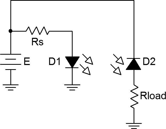
- Figure 1 shows an emitter/detector pair. These devices will emit and detect light at the same wavelength and tend to not produce or detect light at other wavelengths. This aids in avoiding interference. The detector is configured in photoconductive mode. Its current will increase with increasing light level. This current also flows through Rload meaning that Vload will be proportional to light level.
- Build the circuit of Figure 1 using E = 7 volts, Rs = 470 Ω and Rload = 33 kΩ. The emitter diode is denoted with a yellow dot on its case while the detector diode shows a red dot. It is very important that the pair properly be aligned. The bubbles should face each other and cases should be at same height, effectively aiming one bubble at the other. Further, they should only be a few millimeters apart. Finally, the short leads indicate the cathodes.
- Energize the circuit. Because this pair operates in the infrared, nothing will be apparent to the human eye. Verify that the emitter is operating by measuring the voltage across it. It should be in the vicinity of 1.1 volts.
- Measure Vload and record the value in Table 2.
- Slip an opaque card such as a thin piece of black plastic or cardboard between the emitter/detector pair. Measure and record Vload in Table 2.
Data Tables
| Variation | VLED-YELLOW | VLED-BLUE |
|---|---|---|
| Normal | ||
| Dark | ||
| Bright |
| Variation | VLOAD |
|---|---|
| Open | |
| Blocked |
Questions
- What is the effect of light intensity on the LED when used in photovoltaic mode?
- What influence does the color of the LED have on the voltage produced when used in photovoltaic mode?
- What is the correlation between Vload and light level in Figure 1? Give at least two examples of where this effect might be put to good use.
- Why might an infrared emitter/detector system be used in consumer electronics in place of ordinary visible light emitter/detectors?
