
6 The Zener Diode
Learning Objective
Theory Overview
When forward biased, the Zener diode behaves similarly to an ordinary switching diode, that is, it incurs a
0.7 volt drop for silicon devices. Unlike a switching diode, the Zener is normally placed in reverse bias. If the circuit potential is high enough, the Zener will exhibit a fixed voltage drop. This is called the Zener potential or VZ. Manufacturer’s specify this voltage with respect to the Zener test current, or IZT; a point past the knee of the voltage-current curve. That is, if the Zener’s current is at least equal to IZT, then its voltage is approximately equal to the rated VZ. Above this current, even very large increases in current will produce only very modest changes in voltage. Therefore, for basic circuit analysis, the Zener can be replaced mathematically by a fixed voltage source equal to VZ. In practice, some series resistance is usually required to limit the current to a value below the Zener’s maximum in order to prevent damage.
Equipment
| (1) Adjustable DC power supply | model: | srn: |
| (1) DMM | model: | srn: |
| (1) Zener diode around 5.1 volts (NZX5V1B, 1N751) | ||
| (1) 2.2 k Ω resistor ¼ watt | actual: | |
| (1) 4.7 k Ω resistor ¼ watt | actual: | |
Links
Download the datasheets listed below:
Schematics
Procedure
Reverse Curve
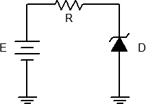
- Consider the circuit of Figure 1 using R = 2.2 kΩ. For any positive value of E the Zener is reverse biased. Until the Zener potential is reached, the diode resistance is effectively infinite and thus no current flows. In this case the voltage across R is zero due to Ohm’s law. Consequently, all of E should appear across the Zener. Once the source exceeds the Zener voltage, the remainder of E (i.e. E minus the Zener potential) drops across R. Thus, as E increases, the circulating current increases but the voltage across the zener remains steady.
- Build the circuit of Figure 1 using R = 2.2 kΩ. Set E to 0 volts and measure both the diode’s voltage and current and record the results in Table 1. Repeat this process for the remaining source voltages listed.
- From the data collected in Table 1, plot the current versus voltage characteristic of the reverse biased diode. Make sure VD is the horizontal axis with ID on the vertical.
Practical Analysis
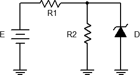
- Consider the circuit of Figure 2 using R1 = 2.2 kΩ and R2 = 4.7 kΩ. In general, to analyze circuits like this, first assume that the Zener is out of the circuit and then compute the voltage across R2 using the voltage divider rule. If the resulting voltage is less than the Zener potential then the Zener is inactive (high resistance) and does not affect the circuit. If, on the other hand, the resulting voltage is greater than the Zener potential then the Zener is active and will limit the voltage across R2 to VZ. Via KVL, the remainder of the voltage drops across R1 and from this the supply current may be determined. This current will then split between R2 and the Zener. The R2 current is found using Ohm’s law. The Zener current is then found via KCL. Note that for higher and higher values of E, the voltage across (and therefore the current through) R2 does not change. Instead, all of the “excess” current from the source passes through the Zener.
- Build the circuit of Figure 2 using R1 = 2.2 kΩ and R2 = 4.7 kΩ. Set E to 2 volts. Compute the theoretical diode voltage and current, and record them in the first row of Table 2. Then measure the diode current and voltage and record in Table 2. Finally, compute and record the deviations.
- Repeat step 5 for the remaining source voltages in Table 2.
Computer Simulation
- Repeat steps 5 and 6 using a simulator, recording the results in Table 3.
Data Tables
| E (volts) | VD | ID |
|---|---|---|
| 0 | ||
| 1 | ||
| 2 | ||
| 5 | ||
| 10 | ||
| 15 | ||
| 20 |
| E (volts) | VD Theory | ID Theory | VD Exp | ID Exp | % Dev VD | % Dev ID |
|---|---|---|---|---|---|---|
| 2 | ||||||
| 5 | ||||||
| 10 | ||||||
| 15 | ||||||
| 20 |
| E (volts) | VD Sim | ID Sim |
|---|---|---|
| 2 | ||
| 5 | ||
| 10 | ||
| 15 | ||
| 20 |
Questions
- Is it safe to assume that the voltage across a Zener is always equal to the rated VZ? Why/why not?
- The instantaneous resistance (also known as AC resistance) of a diode may be approximated by taking the differences between adjacent current-voltage readings. That is, rdiode = ΔVdiode/ΔIdiode. What is the smallest effective resistance of the Zener using Table 1 (show work)?
- If the circuit of Figure 1 had been constructed with the Zener flipped, how would this effect the results recorded in Table 1?
- Assume that a diode with a much higher IZT rating (say, 100 mA) was used in this exercise. In general, what would the likely outcome be for the circuit of Figure 2?
