
2 Resistive Sensors
Learning Objective
The objective of this exercise is to investigate devices that can be used to sense environmental factors such as light and temperature. These are important if circuitry is to react to surrounding conditions, for example, controlling fan speed that is proportional to temperature or turning lights on or off depending on existing light levels. Two such devices are the light dependent resistor or LDR, and the thermistor or temperature dependent resistor. They can be thought of as resistors whose values depend on either the surrounding light levels or the temperature.
Theory Overview
One typical LDR is the CdS (Cadmium Sulfide) cell. The resistance of the CdS cell is inversely proportional to light levels. In darkness, it may exhibit a resistance of tens or even hundreds of kilo ohms. Under high brightness, the resistance may be as little as a few hundred ohms. Thermistors come in two types: PTC or Positive Temperature Coefficient whose resistive value increases with temperature, and NTC or Negative Temperature Coefficient whose resistance decreases with increasing temperature. In contrast, ordinary resistors are designed to be immune to temperature change as much as possible.
One way of using these devices is by placing them in a voltage divider. The resulting voltage will reflect the light levels or temperature. Depending on the position of the device, the voltage can be made to either increase or decrease as the environmental factor increases. For example, the voltage could rise as temperature rises but it could also be designed to have the voltage decrease as temperature rises. Both functions have their uses. Finally, it is worth noting that these devices do not necessarily respond immediately to environmental changes. For example, a thermistor might be used to sense air temperature. If the air temperature were to suddenly rise, there would be some time lag in the response of the thermistor. This is due to the fact that the thermistor itself has mass and requires some time to either heat up or cool down.
Equipment
| (1) Adjustable DC power supply | model: | sm: |
| (1) DMM | model: | sm: |
| (1) Non-diffuse light source (pen light) | ||
| (1) Heat source (diffused light duty heat gun or blow dryer) | ||
| (1) Nominal 1 k Ω – 10 k Ω CdS cell (GL5528) | ||
| (1) 10 k Ω @ 25°C NTC thermistor (Vishay NTCLE100E3) | ||
| (1) 10 k Ω resistor ¼ watt | actual: | |
Schematics
Procedure
LDR
- Use the DMM to measure the resistance of the LDR. Do this away from any windows and do not block ambient room lighting from hitting the device. Record the resistance value in Table 1 under “Normal”.
- Place a finger over the LDR to block all light, making sure that the leads are not also touched. Record the resulting resistance value under “Dark”.
- Shine the pen light directly onto the LDR at a distance of about 25 centimeters. Record the result under “Bright”.
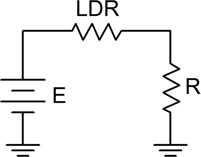
- Construct the circuit of Figure 1 using E=10 volts and R=10 k Ω. Using the voltage divider rule, determine the expected value for the voltage across R under normal lighting and then measure the voltage. Record these values in Table 2.
- Repeat step 4 for the Dark and Bright conditions.
- Finally, slowly move the pen light toward and away from the LDR. Note what happens to the voltage, recording the maximum and minimum voltages obtained in Table 3.
Thermistor
- Use the DMM to measure the resistance of the LDR at room temperature and record the result in Table.
- Do not handle the device excessively as body heat may affect it.
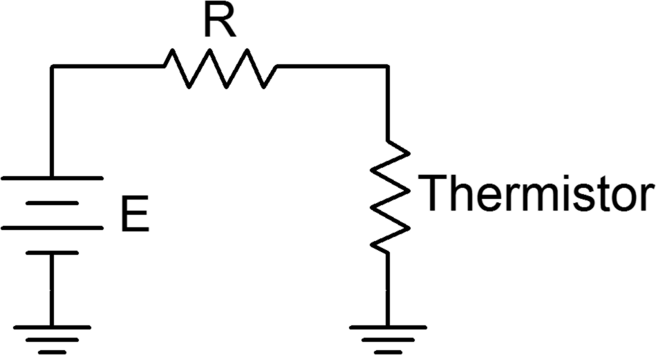
- Build the circuit of Figure 2 using E=10 volts and R=10 kΩ. Measure the voltage across the thermistor and record it in Table 5 under “Room Temp”.
- Monitor the thermistor voltage while applying heat. Caution: If you are using a standard heat gun, place it on a low setting, use a diffuser or keep the gun at least a half meter away to avoid possibly damaging connecting wires or the protoboard. After 30 to 60 seconds, record the thermistor voltage in Table 5. Turn off the heat source and note how long it takes the thermistor circuit to recover back to the original reading.
Data Tables
| Variation | Resistance |
|---|---|
| Normal | |
| Dark | |
| Bright |
| Variation | VR Theory | VR Experiment | % Deviation |
|---|---|---|---|
| Normal | |||
| Dark | |||
| Bright |
| Variation | VR |
|---|---|
| Maximum | |
| Minimum |
| R at room temperature |
| Variation | Vthermistor |
|---|---|
| Room Temp | |
| Hot |
Questions
- If the LDR and resistor positions had been swapped, how would the values of Table 2 change?
- Would the voltages measured in Table 2 change appreciably if R had been 1 kΩ instead of 10 kΩ?
- If the positions of the thermistor and resistor in Figure 2 had been swapped, how would the Table 5 values change?
- If 20 volt power sources had been used, how would the values of Tables 2 and 5 change, if at all?
