
11 The DC Power Supply Project
Learning Objective
- Analysis of the circuit
- Electronic Assembly of all components.
- Testing, evaluation and troubleshooting.
- Report Development
- Report Presentation
Theory Overview
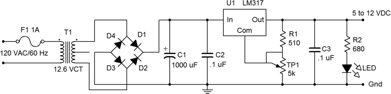
The circuit is an adjustable 5 to 12 VDC supply utilizing a full-wave bridge and integrated voltage regulator. It picks up where the preceding Full-wave Rectifier exercise left off.
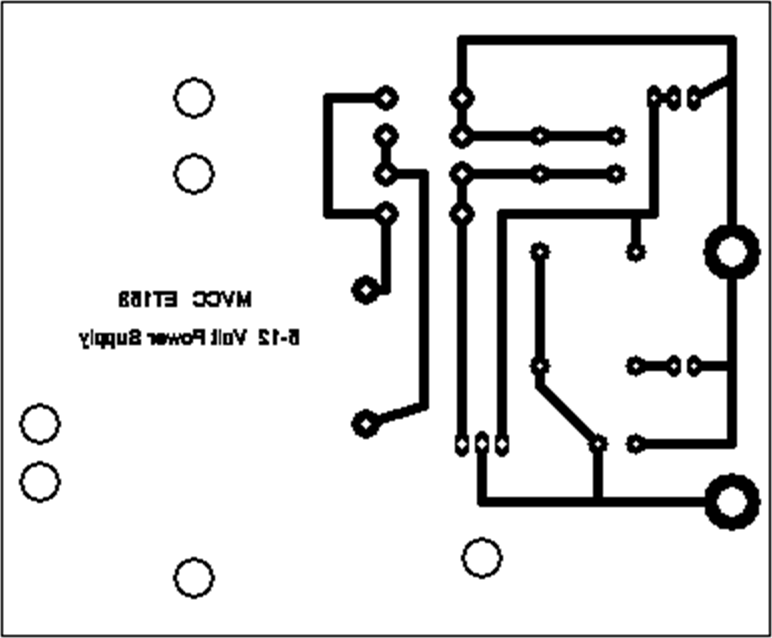
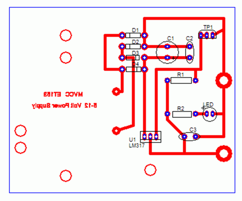
Schematic and Artwork
5 – 12 Volt DC Power Supply Bill of Materials
| Item | Component ID | Description | Part Number | Quantity |
|---|---|---|---|---|
|
1 |
T1 |
117 – 12.6 Volt center tapped transformer |
1 |
|
| 2 | D1-D4 | Rectifier diode | 1N4001 | 4 |
| 3 | C1 | 1000 microfarad 25 volt capacitor | 1 | |
| 4 | C2, C3 | 0.1 microfarad 200 volt capacitor | 2 | |
| 5 | R1 | 510 ohm, ± 5%, 0.5 watt | 1 | |
| 6 | R2 | 680 ohm, ± 5%, 0.5 watt | 1 | |
| 7 | TP1 | 5 k ohm trimpot, 10 turn ± 5%, 0.5 watt | 1 | |
| 8 | LED | Red standard light emitting diode | 1 | |
| 9 | U1 | Voltage regulator | LM317T | 1 |
| 10 | Heat sink | 1 | ||
| 11 | Foot pads | 4 | ||
| 12 | Screws | 5 | ||
| 13 | Bolts | 5 | ||
| 14 | Washers | 5 | ||
| 15 | Wire tie | 1 | ||
| 16 | Line cord | 1 | ||
| 17 | In-line fuse holder and fuse | 1 |
Report and Presentation Format
Report
The report should be in the following format
Title Page – Includes Project Title, Course and Number, Name and Date
Description – Discuss the purpose and nature of the project.
Theory – Develop a block diagram for the circuit. Identify all the components that comprise each segment of the block diagram and describe their operation in terms of inputs and outputs. Include a listing of the specifications for the supply as follows:
-
-
- Input power: 117 VAC RMS, ± 10%, 50 – 60 Hz
- Output: 5 to 12 volts DC, adjustable, @ 300 mA with 0.5% ripple
-
Discuss the type of transformer used and describe the type of diode rectifier circuit. Also discuss the tolerance of the resistors in the circuit and the function of the potentiometer?
Equipment – List the special equipment that was used to complete the project.
Components – Refer to the PCB documentation. Include copies of all the printed circuit board documentation and discuss the purpose of each document.
Procedure – Describe the basic assembly and the general verification procedure for checking the power supply function, including circuit board assembly, soldering, and the testing procedures to verify key functions. Be sure to discuss the requirements for a good solder joint, the purpose of the flux in the solder and the need to frequently clean of the tip of the soldering iron. Also, identify the components that are polarity sensitive and discuss the impact of reversing the polarity during assembly.
Data – Record the measurements taken to verify the operation. These should include the Range of Adjustment, the No-Load Output Voltage, the Transformer Secondary Voltage, the Rectifier Voltage Output and the Peak to Peak Ripple at full output load.
Conclusion -What was learned on this project? What went wrong? How was it resolved? List any ideas about how to improve the performance of the power supply.
Oral Presentation
The presentation should be an overview of your report with a focus on your project conclusion. Your presentation will be video recorded.
Report Grading Criteria
| 1 = Below Minimum Standards | 2 = At Minimum Standards | 3 = At Average Standard | 4 = Exceeds Average Standard | |
| Format/Neatness 5% | ||||
| Grammar 5% | ||||
| Thoroughness 10% | ||||
| Theory
Discussion 30% |
||||
| Procedure Discussion
30% |
||||
| Presentation 20% |
Circuit Verification Data Sheet
- Output Voltage and LED Test: LED operational ________
- Output Voltage Range of Adjustment ________ to ________
- Adjust output to 5 VDC with a 20 ohm load resistor attached to the output.
- Calculated Load Current________ Measured Load Current ________
- Calculate the power being dissipated by the 20 ohm resistor? ________
- Calculate the expected turns ratio of the transformer from the transformer data listed on the Bill of Material. Calculate and measure VSec RMS.
- Calculated n =
- Measured VPri RMS =
- Calculated VSec RMS =
- Measured VSec RMS =
- Calculate the expected DC Voltage (VDC) and Peak to Peak Ripple (Vrpp) out of the filter circuit using the formula: Vrpp = ILOAD/fC where f = frequency and C is the value of the filter capacitor. Use a load current of 70 milliamps.
- Calculated VDC =
- Calculated Vrpp =
- Measure the DC Voltage (VDC) and Peak to Peak Ripple (Vrpp) out of the filter circuit values with the 20 ohm resistor in place:
- Measured VDC =
- Measured Vrpp =
- Measure VDC and Vrpp of the output voltage of the power supply with the 20 ohm load resistor in place.
- VDC of the Power Supply Output =
- Vrpp of the Power Supply Output =
