
1.6 Exercises
Analysis Problems
- For the circuit of Figure 1.6.1, determine 𝐼𝐷 and 𝑉𝐷𝑆. 𝐼𝐷𝑆𝑆 = 40 mA, 𝑉𝐺𝑆(𝑜𝑓𝑓) = −4 V, 𝑉𝐷𝐷 = 26 V, 𝑉𝐺𝐺 = −2 V, 𝑅𝐺 = 220 kΩ, 𝑅𝐷 = 1.2 kΩ.
- For the circuit of Figure 1.6.1, determine 𝐼𝐷 and 𝑉𝐷𝑆. 𝐼𝐷𝑆𝑆 = 20 mA, 𝑉𝐺𝑆(𝑜𝑓𝑓) = −3 V, 𝑉𝐷𝐷 = 22 V, 𝑉𝐺𝐺 = −1 V, 𝑅𝐺 = 390 kΩ, 𝑅𝐷 = 1 kΩ.
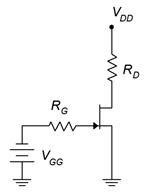
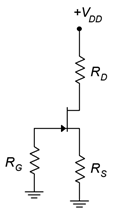
Figure 1.6.1 - For the circuit of Figure 1.6.2, determine 𝐼𝐷, 𝑉𝐺 and 𝑉𝐷. 𝐼𝐷𝑆𝑆 = 24 mA, 𝑉𝐺𝑆(𝑜𝑓𝑓) = −6 V, 𝑉𝐷𝐷 = 36 V, 𝑅𝐺 = 220 kΩ, 𝑅𝑆 = 2 kΩ, 𝑅𝐷 = 1.8 kΩ.
- For the circuit of Figure 1.6.2, determine 𝐼𝐷, 𝑉𝑆 and 𝑉𝐷𝑆. 𝐼𝐷𝑆𝑆 = 18 mA, 𝑉𝐺𝑆(𝑜𝑓𝑓) = −3 V, 𝑉𝐷𝐷 = 30 V, 𝑅𝐺 = 270 kΩ, 𝑅𝑆 = 2.7 kΩ, 𝑅𝐷 = 3.3 kΩ.
- For Figure 1.6.3, determine 𝐼𝐷, 𝑉𝐺 and 𝑉𝐷. 𝐼𝐷𝑆𝑆 = 16 mA, 𝑉𝐷𝐷 = 25 V, 𝑉𝐺𝑆(𝑜𝑓𝑓) = −3 V, 𝑉𝑆𝑆 = −6 V, 𝑅𝐺 = 560 kΩ, 𝑅𝑆 = 2 kΩ, 𝑅𝐷 = 3.6 kΩ.
- For Figure 1.6.3, determine 𝐼𝐷, and 𝑉𝐷𝑆. 𝐼𝐷𝑆𝑆 = 16 mA, 𝑉𝐷𝐷 = 25 V, 𝑉𝐺𝑆(𝑜𝑓𝑓) = −3 V, 𝑉𝑆𝑆 = −9 V, 𝑅𝐺 = 680 kΩ, 𝑅𝑆 = 2 kΩ, 𝑅𝐷 = 2.7 kΩ.
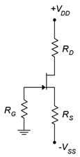
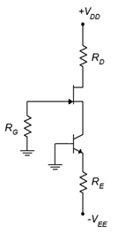
Figure 1.6.3 - For Figure 1.6.4, determine 𝐼𝐷, 𝑉𝐺 and 𝑉𝐷. 𝐼𝐷𝑆𝑆 = 16 mA, 𝑉𝐷𝐷 = 25 V, 𝑉𝐺𝑆(𝑜𝑓𝑓) = −3 V, 𝑉𝐸𝐸 = −9 V, 𝑅𝐺 = 810 kΩ, 𝑅𝐸 = 2 kΩ, 𝑅𝐷 = 2.7 kΩ.
- For the circuit of Figure 1.6.4, determine 𝐼𝐷 and 𝑉𝐷𝑆. 𝐼𝐷𝑆𝑆 = 40 mA, 𝑉𝐺𝑆(𝑜𝑓𝑓) = −4 V, 𝑉𝐷𝐷 = 30 V, 𝑉𝐸𝐸 = −6 V, 𝑅𝐺 = 750 kΩ, 𝑅𝐸 = 500 Ω, 𝑅𝐷 = 1.8 kΩ.
Design Problems
- Using the circuit of Figure 1.6.2, determine a value for 𝑅𝑆 to set 𝐼𝐷 to 4 mA. 𝐼𝐷𝑆𝑆 = 10 mA, 𝑉𝐺𝑆(𝑜𝑓𝑓) = −2 V, 𝑉𝐷𝐷 = 20 V, 𝑅𝐺 = 430 kΩ, 𝑅𝐷 = 1.8 kΩ.
- Using the circuit of Figure 1.6.1, determine a value for 𝑉𝐺𝐺 to set 𝐼𝐷 to 2 mA. 𝐼𝐷𝑆𝑆 = 10 mA, 𝑉𝐺𝑆(𝑜𝑓𝑓) = −4 V, 𝑉𝐷𝐷 = 28 V, 𝑅𝐺 = 470 kΩ, 𝑅𝐷 = 4.7 kΩ.
- Using the circuit of Figure 10.6.410.6.4, determine a value for 𝑅𝐸 to set 𝐼𝐷 to 4 mA. 𝐼𝐷𝑆𝑆 = 18 mA, 𝑉𝐺𝑆(𝑜𝑓𝑓) = −3 V, 𝑉𝐷𝐷 = 25 V, 𝑉𝐸𝐸 = −12 V, 𝑅𝐺 = 330 kΩ, 𝑅𝐷 = 2.2 kΩ.
- Using the circuit of Figure 1.6.4, determine values for 𝑅𝐸 and 𝑅𝐷 to set 𝐼𝐷 to 5 mA and 𝑉𝐷 to 6 V. 𝐼𝐷𝑆𝑆 = 20 mA, 𝑉𝐺𝑆(𝑜𝑓𝑓) = −4 V, 𝑉𝐷𝐷 = 32 V, 𝑉𝐸𝐸 = −10 V, 𝑅𝐺 = 390 kΩ.
Challenge Problems
- Following the derivation of Equation 10.4.2, derive Equation 10.4.4.
- Using the circuit of Figure 1.6.3, determine values for 𝑅𝑆 and 𝑉𝑆𝑆 to set 𝐼𝐷 to 4 mA. 𝐼𝐷𝑆𝑆 = 16 mA, 𝑉𝐺𝑆(𝑜𝑓𝑓) = −4 V, 𝑉𝐷𝐷 = 30 V, 𝑅𝐺 = 680 kΩ, 𝑅𝐷 = 2 kΩ.
Computer Simulation Problems
- Perform a DC operating point simulation on the circuit of Problem 7 to verify the results. The J111 will be sufficient.
- Perform a DC operating point simulation on the circuit of Problem 10 to verify the results. The J111 will be sufficient.
Department of Marginal Utility
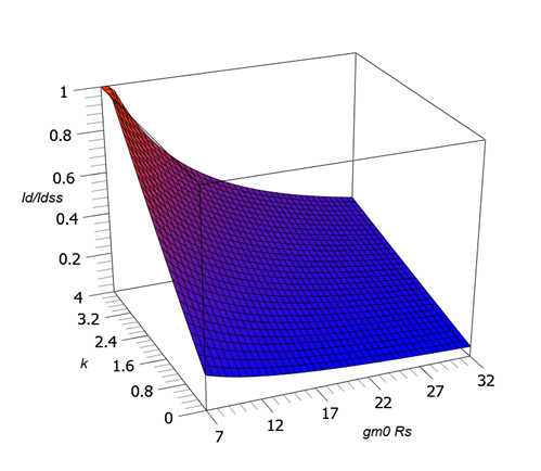
The graphs of Figure 10.4.13 represent three slices from this surface.
Looks cool, but…
