
9.7 Problems
Review Questions
- Give two examples of how negative feedback is used in everyday life.
- What circuit parameters will negative feedback alter, and to what extent?
- What is meant by the term “Sacrifice Factor”?
- What is the usage of Gain and Phase Margin?
- Name the different negative feedback connections (i.e., variants or forms).
- How might negative feedback accidentally turn into positive feedback?
- What circuit parameters won’t negative feedback effect?
- In practical amplifiers, when does negative feedback “stop working”, and why?
Problems
Analysis Problems
- An amplifier’s open-loop gain plot is given in Figure 3.7.1 . If the amplifier is set up for a closed-loop gain of 100, what is the sacrifice factor ( 𝑆 ) at low frequencies? What is 𝑆 at 1 kHz?
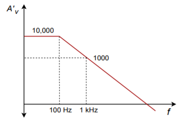
Figure 3.7.1 - If the amplifier in Problem 1 has an open-loop THD of 5%, what is the closed-loop THD at low frequencies? Assuming that the open-loop THD doesn’t change with frequency, what is the closed-loop THD at 1 kHz?
- If an amplifier has an open-loop response as given in Figure 3.7.1 , and a feedback factor ( 𝛽 ) of 0.05 is used, what is the exact low frequency closed loop gain? What is the approximate low frequency gain? What is the approximate gain at 1 kHz?
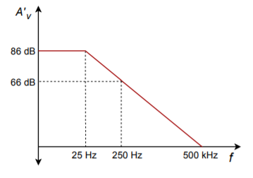
Figure 3.7.1 - Using the open loop response curve in Figure 3.7.2 , determine exact and approximate values of 𝛽 for a closed-loop gain of 26 dB.
- Determine the closed-loop 𝑓2 for the circuit of Problem 4.
- What is the maximum allowable phase shift at 500 kHz for stable usage of negative feedback in Figure 3.7.2 ?
- Determine the gain and phase margins for the amplifier response given in Figure 3.7.3 . Is this amplifier a good candidate for negative feedback?

Figure 3.7.3 - Determine the closed-loop (mid-band) gain in Figure 3.7.4 .
- What is the closed-loop 𝑍𝑖𝑛 in Figure 3.7.4 ? What is 𝑍𝑜𝑢𝑡 ?
- What is the low-frequency sacrifice factor in Figure 3.7.4?
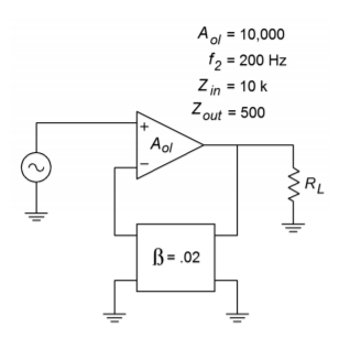
Figure 3.7.4 - How much distortion reduction can we hope for in Figure 3.7.4 ?
- How much of a signal/noise improvement can we expect in Figure 3.7.4?
- Assuming 𝑉𝑖𝑛(𝑡)=0.1sin2𝜋500𝑡 , in Figure 3.7.4 , what is 𝑉𝑜𝑢𝑡(𝑡) ?
- If the circuit in Figure 3.7.4 had an open-loop 𝑓1 of 10 Hz, what would the closed-loop 𝑓1 be?
- Determine an appropriate pair of resistors to set 𝛽 to 0.1 in Figure 3.7.4 .
Challenge Problems
- If the feedback network of Figure 3.7.4 produces a phase shift of -200 ∘ at 4 kHz, what effect will this have on circuit operation in Problem 10?
- Consider the circuit of Figure 3.4.4. In general, what effect will the following alterations to the feedback network have on the closed loop system response? A) Placing a capacitor across 𝑅𝑓 B) Placing a capacitor across 𝑅𝑖 C) Placing a rectifying diode across 𝑅𝑓 (both polarities).
Computer Simulation Problems
- Rerun the simulation of Figure 3.4.5 using the following open loop gains: 1 k, 10 k, and 100 k. What can you conclude from the results?
- Verify the results of Problem 13 using a circuit simulator. It is possible to extend the basic op amp model with a lag network in order to mimic 𝑓2−𝑜𝑙 .
- Verify the stability of the circuit used in Problem 13 with regard to the open loop gain. Run simulations with the given 𝐴𝑜𝑙 , and with values one decade above and below. Compare the resulting simulations and determine the maximum deviation of 𝐴𝑠𝑝 .
