
12.6 Extended Topic – Primary Switcher
The switching regulators examined earlier are referred to as secondary switchers because the switching elements are found on the secondary side of the power transformer. In contrast to this is the primary or forward switcher. The switching circuitry in these designs is placed prior to the primary of the power transformer. This positioning offers a distinct advantage over the secondary switcher. The power transformer and secondary rectifier will be handling much higher frequencies, thus they can be made much smaller. The result is a physically smaller and lighter design.
One possible configuration of a primary switcher is shown in Figure 8.6.1 . This is known as a push-pull configuration. The two power transistors are alternately pulsed on and off. That is, when one device is conducting, the other is off. By doing this, opposite polarity pulses are fed into the primary of the transformer, creating a high frequency alternating current (as is the case with secondary switchers, primary switchers operate at frequencies well above the nominal 60 Hz power line). This high frequency waveform is then stepped up or down to the secondary, where it is again rectified and then filtered, producing a DC output signal.
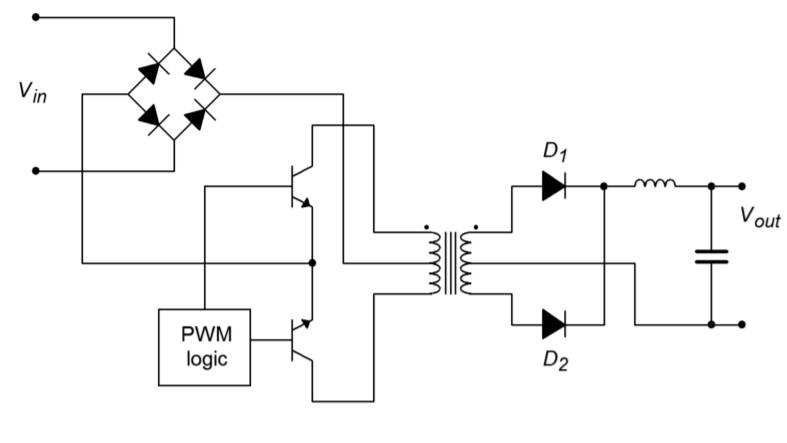
Although the transformer and secondary rectifier/filter may be reduced in size, it is important to note that the main input rectifier and switching transistors are not isolated from the AC power source, as is the case in other power supply designs. These devices must handle high input potentials. For an ordinary 120 V AC line, that translates to over 170 V peak. Also, the power transistors will see an off-state potential of twice 𝑉𝑖𝑛, or over 340 V in this case. Some form of in-rush current limiting will also need to be added.
A somewhat more sophisticated approach is taken in Figure 8.6.2 . This circuit is known as a full bridge switcher. In this configuration, diagonal pairs of devices are simultaneously conducting (i.e., 𝑄1/𝑄4 and 𝑄2/𝑄3 ). By eliminating the center-tapped primary, each device sees a maximum potential of 𝑉𝑖𝑛, or one-half that of the pushpull switcher. The obvious disadvantage is the need for four power devices instead of just two.
Primary switchers do offer a size and weight advantage over secondary switchers and linear regulators. They also maintain the high efficiency characteristics of the secondary switcher. They do tend to be somewhat more complex, though, and their application is therefore best suited to cases where circuit size, weight, and efficiency are paramount.

