
13.5 Problems
Review Questions
- How does positive feedback differ from negative feedback?
- Define the Barkhausen criterion.
- Explain the operation of the Wien bridge op amp oscillator.
- Detail the operation of the phase shift op amp oscillator.
- How might a square wave be generated from a sinusoidal or triangular source?
- Give two ways to make the output frequency of a Wien bridge oscillator user-adjustable.
- What factors contribute to the accuracy of a Wien bridge oscillator’s output frequency?
- What is a VCO, and how does it differ from a fixed-frequency oscillator?
- Draw a block diagram of a PLL and explain its basic operation.
- What is the difference between capture range and lock range for a PLL?
- Give at least two applications for a fixed-frequency oscillator or VCO.
- Give at least two applications for the PLL.
- Explain the difference between astable and monostable operation of a timer.
Problems
Analysis Problems
Unless otherwise specified, all circuits use ± 15 V power supplies.
- Given the circuit of Figure 9.5.1 , determine the frequency of oscillation if 𝑅1=1.5𝑘Ω , 𝑅2=𝑅3=𝑅4=3𝑘Ω , and 𝐶1=𝐶2=22𝑛𝐹 .

Figure 9.5.1 - Given the circuit of Figure 9.5.1 , determine the frequency of oscillation if 𝑅2=22𝑘Ω , 𝑅1=𝑅3=𝑅4=11𝑘Ω , and 𝐶1=𝐶2=33𝑛𝐹 .
- Given the circuit of Figure 9.5.2 , determine the maximum and minimum fo if 𝑅1=5.6𝑘Ω , 𝑅2=12𝑘Ω , 𝑅3=𝑅4=1𝑘Ω , 𝑃1=𝑃2=10𝑘Ω , 𝐶1=𝐶2=39𝑛𝐹 .
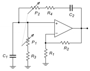
Figure 9.5.2 - Given the circuit of Figure 9.5.3 , determine fo if 𝑅4=2𝑘Ω , 𝑅3=20𝑘Ω , 𝑅2=200𝑘Ω , 𝑅1=1.6𝑀Ω , 𝐶1=30𝑛𝐹 , 𝐶2=3𝑛𝐹 , 𝐶3=300𝑝𝐹 .

Figure 9.5.3 - Given the circuit of Figure 9.5.3 , determine 𝑓𝑜 if 𝑅1=𝑅3=𝑅4=3.3𝑘Ω , 𝑅2=100𝑘Ω , 𝐶1=𝐶2=𝐶3=86𝑛𝐹 .
- Given the circuit of Figure 9.5.4 , determine 𝑓𝑜 if 𝑅1=𝑅2=22𝑘Ω , 𝑅3=33𝑘Ω , 𝐶=3.3𝑛𝐹 .

Figure 9.5.4 - Using the circuit of Figure 9.5.5 , determine the output voltage if 𝑅𝑠𝑒𝑡=100𝑘 .
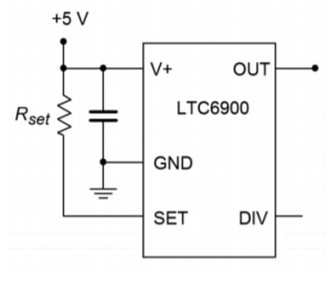
Figure 9.5.5 - Using the circuit of Figure 9.5.6 , determine the output voltage if 𝑅𝑠𝑒𝑡=50𝑘 .
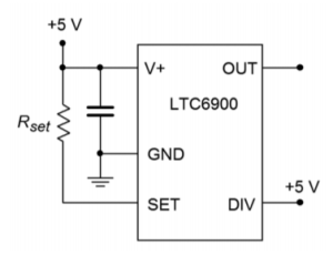
Figure 9.5.6 - A temperature dependent resistor, or thermistor, is used in Figure 9.5.7 . If the resistance varies between 20 k and 200 k through the temperature range of interest, determine the range of output frequencies.
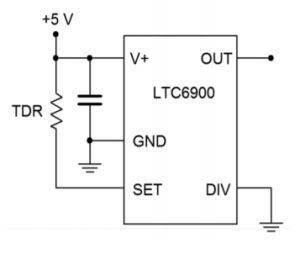
Figure 9.5.7 - For the circuit of 9.5.8 , determine the range of output frequencies if 𝑉𝐶 varies between 0 V and -1 V. 𝑅𝐶=100𝑘 , 𝑅1=1𝑀 , 𝑅2=681𝑘 .
- For the circuit of Problem 9.10, determine the output frequencies if 𝑉𝑐 is a 100 Hz square wave at 0.5 volts peak.
- Sketch the output waveform for Problem 9.11.

Figure 9.5.8 - If a control voltage of 0.4 sin 2π60t is used for the circuit of Problem 9.10, find the resulting maximum and minimum output frequencies.
- Given the circuit of Figure 9.5.9 , determine the output frequency if 𝑉𝐶=2𝑉 , 𝑅𝑉𝐶𝑂=𝑅𝑠𝑒𝑡=100𝑘 , 𝑅1=976𝑘 and 𝑅2=102𝑘 .
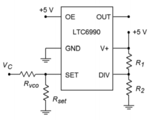
Figure 9.5.9 - Given the circuit of Figure 9.5.4 , determine fo if 𝑅1=𝑅2=22𝑘Ω , 𝑅3=33𝑘Ω , and 𝐶=3.3𝑛𝐹 .
- Determine the output frequency range in Figure 9.5.10 if 𝑉𝐶 varies from 0 to 2 volts, 𝑅𝑓=200𝑘 , 𝑅𝑖=100𝑘 , 𝑅𝐶=500𝑘 , 𝑅1=976𝑘 and 𝑅2=182𝑘 .

Figure 9.5.10 - Determine the output frequency range in Figure 9.5.11 if 𝑉𝑏 varies from 0 to 2 volts, 𝑉𝑎=1𝑣𝑜𝑙𝑡 , 𝑅𝑓=200𝑘 , 𝑅𝑎=100𝑘 , 𝑅𝑏=200𝑘 , 𝑅𝐶=390𝑘 , 𝑅1=182𝑘 and 𝑅2=976𝑘 .
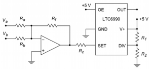
Figure 9.5.11
Design Problems
- For the circuit of Figure 9.5.1 , determine values for 𝐶1 and 𝐶2 if 𝑅1=6.8𝑘Ω , 𝑅2=𝑅3=𝑅4=15𝑘Ω , and 𝑓𝑜=30𝑘𝐻𝑧 .
- For the circuit of Figure 9.5.1 , determine values for 𝑅3 and 𝑅4 if 𝑅1=2.2𝑘Ω , 𝑅2=4.7𝑘Ω , 𝐶1=𝐶2=47𝑛𝐹 , and 𝑓𝑜=400𝐻𝑧 .
- For the circuit of Figure 9.5.1 , determine values for 𝑅2,𝐶1 and 𝐶2 if 𝑅1=7.2𝑘Ω,𝑅3=𝑅4=3.9𝑘Ω , and 𝑓𝑜=19𝑘𝐻𝑧 .
- Determine the values required for 𝑅3,𝑅4,𝑃1 , and 𝑃2 in Figure 9.5.2 if 𝐶1=𝐶2=98𝑛𝐹 , 𝑅1=5.6𝑘Ω,𝑅2=12𝑘Ω , 𝑓𝑜.𝑚𝑖𝑛=2𝑘𝐻𝑧 , and 𝑓𝑜.𝑚𝑎𝑥=20𝑘𝐻𝑧 .
- Repeat Problem 21 for 𝑓𝑜.𝑚𝑖𝑛=10𝑘𝐻𝑧 and 𝑓𝑜.𝑚𝑎𝑥=30𝑘𝐻𝑧 .
- Redesign the circuit of Problem 1 so that exact gain resistors are not needed. Use Figure 9.6 as a model.
- Redesign the circuit of Problem 3 so that clipping does not occur. Use Figure 9.2.6 as a model.
- Determine new values for the capacitors of Problem 4 if fo is changed to 10 kHz.
- Given the circuit of Figure 9.5.3 , determine values for the capacitors if 𝑅1=𝑅3=𝑅4=3.3𝑘Ω , 𝑅2=100𝑘Ω , and 𝑓𝑜=7.6𝑘𝐻𝑧 .
- Given the circuit of Figure 9.5.3 , determine values for the resistors if the capacitors all equal 1100 pF and fo = 15 kHz.
- Determine the capacitor and resistor values for the circuit of Figure 9.5.3 if 𝑅2=56𝑘Ω and 𝑓𝑜=1𝑘𝐻𝑧 .
- Find C in Figure 9.5.4 if 𝑓𝑜=5𝑘𝐻𝑧,𝑅1=𝑅3=39𝑘Ω,𝑅2=18𝑘Ω .
- Determine the resistor values in Figure 9.5.4 if 𝑓𝑜=20𝑘𝐻𝑧 and 𝐶=22𝑛𝐹 . Set 𝑅1=𝑅2 and 𝑅2=𝑅3/2 . Sketch the output waveforms as well.
- Determine the required ratio for 𝑅2/𝑅3 to set the triangle wave output to 5 V peak in Figure 9.5.4 .
- Using the circuit of Figure 9.5.5 , find 𝑅𝑠𝑒𝑡 for an output of 100 kHz.
- Determine the value for 𝑅𝑠𝑒𝑡 in Figure 9.5.6 to set the frequency to 50 kHz.
- Design a square wave generator that is adjustable from 5 kHz to 20 kHz.
- For the circuit of Figure 9.5.9 , determine the component values such that a frequency of 250 kHz is produced when 𝑉𝐶=0 volts and 125 kHz when 𝑉𝐶 is 1 volt.
- Design a 𝑉𝐶𝑂 circuit and determine the component values such that a frequency of 250 kHz is produced when 𝑉𝐶=1 volt and 125 kHz when 𝑉𝐶 is 0 volts.
Challenge Problems
- Using Figure 9.2.9 as a guide, design a sine wave oscillator that will operate from 2 Hz to 20 kHz, in decade ranges
- Design a 10 kHz TTL-compatable square wave oscillator using a Wien bridge oscillator and a 311 comparator.
- Using a triangle or sine wave oscillator and a comparator, design a variable duty cycle pulse generator. Hint: Consider varying the comparator
reference. - Using a function synthesizer (Chapter Seven) and the oscillator of Figure 9.5.4 , outline a simple laboratory frequency generator with sine, triangle, and square wave outputs.
- For the preceding problem, outline how amplitude and DC offset controls could be implemented as well.
- Generate a square wave that smoothly increases from 50 kHz to 300 kHz and back at a rate 100 times each second.
- Assume that the output of the left-most op amp of Figure 9.5.4 drives Vb of Figure 9.5.11 . Further, assume that a positive DC voltage equal to the peak
value of 𝑉𝑏 is used to drive 𝑉𝑎 . Also, 𝑅𝑎=𝑅𝑏=𝑅𝑓 . Assuming the frequency produced by Figure 9.5.4 is considerably lower than that of Figure 9.5.11 , describe the output waveform of Figure 9.5.11 .
Computer Simulation Problems
- Perform a simulation of the circuit of Problem 1. Perform a frequency domain analysis of the positive feedback loop’s gain and phase, and verify that the Barkhausen Criterion is met.
- Perform a simulation for the circuit of Problem 4. Perform a frequency domain analysis of the positive feedback loop’s gain and phase, and verify that the Barkhausen Criterion is met.
- Perform a time-domain simulation analysis for the circuit of Problem 6. Make sure that you check both outputs (a simultaneous plot would be best).
