15.4 Filter Order and Poles
The rate at which a filter’s response falls in the transition band is determined by the filter’s order. The higher the order of a filter, the faster its rolloff rate is. The order of a filter is given as an integer value and is derived from the filter’s transfer function. As an example, all other factors being equal, a fourth-order filter will roll off twice as fast as a second-order filter, and four times faster than a first-order unit. The order of a filter also indicates the minimum number of reactive components that the filter will require. For example, a third-order filter requires at least three reactive components: one capacitor and two inductors, two capacitors and one inductor, or in the case of an active filter, three capacitors. Related to this is the number of poles that a filter utilizes. It is common to hear descriptions such as “a four-pole filter”. For most general-purpose high- or low-pass filters, the terms pole and order may be used interchangeably and completely describe the rolloff rate. For more complex filters this isn’t quite the case, and you may also hear descriptions such as “a sixpole, two-zero filter”. Because this chapter is an introduction to filters, we will not detail the operation of these more esoteric types. Suffice it to say that when a circuit is described as an 𝑁𝑡ℎ -order filter, you may assume that it is an 𝑁 -pole filter, as well.
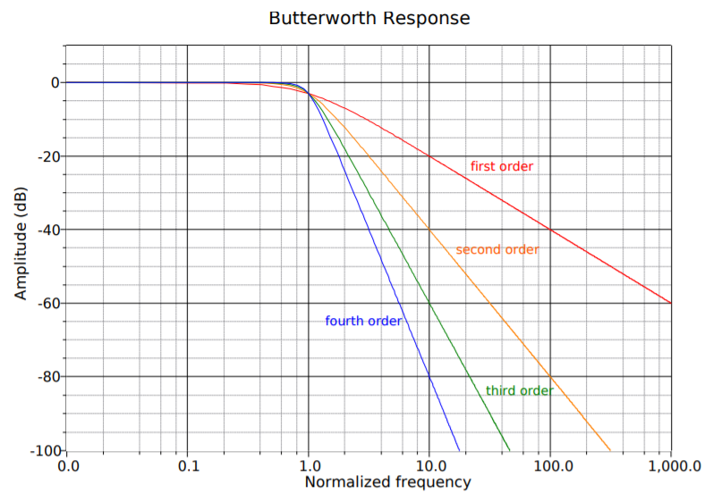
A general observation can be given that the rolloff rate of a filter will eventually approach 6 dB per octave per pole (20 dB per decade per pole). Therefore, a thirdorder filter (i.e., three-pole) eventually rolls off at a rate of 18 dB per octave (60 dB per decade). We say “eventually” because the response around the break frequency may be somewhat faster or slower than this value. Figure 11.4.1 compares the effect of order on four otherwise identical low-pass filters. Note that the higher order filters offer greater attenuation at any frequency beyond the break point. As with most response plots, Figure 11.4.1 utilizes decibel instead of ordinary gain. Also, these filters are shown with unity gain in the pass band, although this doesn’t have to be the case. High-order filters are used when the transition band needs to be as narrow as possible. It is not uncommon to see twelfth-order and higher filters used in special applications. As you might guess, higher order filters are more complex and costly to design and build. For many typical applications, orders in the range of two to six are common.