
14.8 Problems
Review Questions
- What is the basic function of an integrator?
- What is the basic function of a differentiator?
- What is the function of the capacitor in the basic integrator and differentiator?
- Why are capacitors used in favor of inductors?
- What practical modifications need to be done to the basic integrator, and why?
- What practical modifications need to be done to the basic differentiator, and why?
- What are the negative side effects of the practical versus basic integrator and differentiator?
- What is an analog computer, and what is it used for?
- What are some of the advantages and disadvantages of the analog computer versus the digital computer?
- How might integrators and differentiators be used as wave-shaping circuits?
Problems
Analysis Problems
- Sketch the output waveform for the circuit of Figure 10.8.1 if the input is a 4 V peak square wave at 1 kHz.

Figure 10.8.1 - Repeat Problem 1 if 𝑉𝑖𝑛(𝑡)=5sin2𝜋318𝑡 .
- Repeat Problem 1 if 𝑉𝑖𝑛(𝑡)=20cos2𝜋10000𝑡 .
- Using the circuit of Problem 1, if the input is a ramp with a slope of 10 V/s, find the output after 1 ms, 10 ms, and 4 s. Sketch the resulting wave.
- Determine the low frequency gain for the circuit of Figure 10.8.2 .
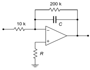
Figure 10.8.2 - If 𝐶=33 nF in Figure 10.8.2 , determine 𝑉𝑜𝑢𝑡if 𝑉𝑖𝑛is a 200 mV peak sine wave at 50 kHz.
- Repeat Problem 6 using a 200 mV peak square wave at 50 kHz.
- Sketch the output of the circuit of Figure 10.2.7 with the input signal given in Figure 10.8.3 .
- Assume that the input to the circuit of Figure 10.2.7 is 100 mV DC. Sketch the output waveform, and determine if it goes to saturation.
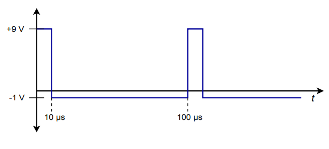
Figure 10.8.3 - Sketch the output waveform for Figure 10.2.7, given an input of: 𝑉𝑖𝑛(𝑡)=0.5cos2𝜋9000𝑡 .
- Given the circuit of Figure 10.8.4 , sketch the output waveform if the input is a 100 Hz, 1 V peak triangle wave.

Figure 10.8.4 - Repeat Problem 11 if the input is a 2 V peak square wave at 500 Hz. Assume that the rise and fall times are 1 𝜇 s and are linear (vs. exponential).
- Repeat Problem 11 for the following input: 𝑉𝑖𝑛(𝑡)=3cos2𝜋60𝑡 .
- Repeat Problem 11 for the following input: 𝑉𝑖𝑛(𝑡)=0.5sin2𝜋1000𝑡 .
- Repeat Problem 11 for the following input: 𝑉𝑖𝑛(𝑡)=10𝑡2 .

Figure 10.8.5 - Given the input shown in Figure 10.8.5 , sketch the output of the circuit of Figure 10.19.
- Given the input shown in Figure 10.8.5 , sketch the output of the circuit of Figure 10.19.
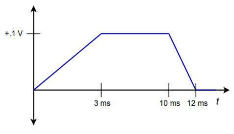
Figure 10.8.6 - Sketch the output waveform for Figure 10.3.9, given an input of 𝑉𝑖𝑛(𝑡)=0.5cos2𝜋4000𝑡 .
- Sketch the output waveform for Figure 10.3.9, if 𝑉𝑖𝑛is a 300 mV peak triangle wave at 2500 Hz.
Design Problems
- Given the circuit of Figure 10.8.1 ,
- Determine the value of 𝐶 required in order to yield an integration constant of −2000.
- Determine the required of value of 𝑅 for minimum integration offset error.
- Determine 𝑓𝑙𝑜𝑤 .
- Determine the 99% accuracy point.
- Given the differentiator of Figure 10.8.7 , determine the value of 𝑅 that will set the differentiation constant to −103 .

Figure 10.8.7 - Determine the value of 𝑅𝑖 such that the maximum gain is 20 for the circuit of Figure 10.8.7 . (Use the values of Problem 21.)
- Determine the value of 𝐶𝑓 in Problem 22 such that noise above 5 kHz is attenuated.
- Design an integrator to meet the following specifications: integration constant of −4500, 𝑓𝑙𝑜𝑤 no greater than 300 Hz, 𝑍𝑖𝑛 at least 6 k Ω , and DC gain no more than 32 dB.
- Design a differentiator to meet the following specifications: differentiation constant of −1.2𝐸−4 , 𝑓ℎ𝑖𝑔ℎ at least 100 kHz, and a minimum 𝑍𝑖𝑛 of 50 Ω .
Challenge Problems
- Sketch the output waveform for the circuit of Figure 10.2.7 if the input is the following damped sinusoid: 𝑉𝑖𝑛(𝑡)=3𝜀−200𝑡sin2𝜋1000𝑡 .
- A 1.57 V peak, 500 Hz square wave may be written as the following infinite series: 𝑉𝑖𝑛(𝑡)=2∑∞𝑛=112𝑛−1sin2𝜋500(2𝑛−1)𝑡
Using this as the input signal, determine the infinite series output Equation for the circuit of Figure 10.2.7. - Sketch the output for the preceding problem. Do this by graphically adding the first few terms of the output.
- Remembering that the voltage across an inductor is equal to the inductance times the rate of change of current, determine the output Equation for the circuit of Figure 10.8.8 .

Figure 10.8.8 - Repeat the preceding Problem for the circuit of Figure 10.8.9 .

Figure 10.8.9 - A 2.47 V peak, 500 Hz triangle wave may be written as the following infinite series: 𝑉𝑖𝑛(𝑡)=2∑∞𝑛=11(2𝑛−1)2cos2𝜋500(2𝑛−1)𝑡
Using this as the input signal, determine the infinite series output Equation for the circuit of Figure 10.3.9. - Sketch the output for the preceding problem. Do this by graphically adding the first few terms of the output.
Computer Simulation Problems
- Simulate Problem 1 and determine the steady-state response.
- Model Problem 8 using a simulator. Determine both the steady-state and initial outputs.
- Simulate Problem 14. Determine the steady-state output.
- Model Problem 22 using a simulator and determine the output signal.
- Compare the resulting waveform produced by the circuit of Problem 8 using both the 741 op amp and the medium-speed LF411. Does the choice of op amp make a discernible difference in this application?
